elevator traction system

A traction system and elevator technology, applied in the elevator field, can solve the problems of high cost, difficult to guarantee rigidity and strength, limited application, etc., and achieve the effects of good rigidity and strength, saving hoistway space, and high safety factor

Active Publication Date: 2015-10-28
GUANGZHOU GUANGRI ELEVATOR IND
View PDF10 Cites 0 Cited by
  • Summary
  • Abstract
  • Description
  • Claims
  • Application Information

AI Technical Summary

Problems solved by technology

[0005] There are also some designs that use a concave-convex composite steel strip, such as Chinese patent 200810061529.9, which is to change the shape of the composite steel strip, increase the concave-convex surface (or use a V-ribbed belt), and make the concave-convex surface correspondingly on the wheel groove, although it can also be effective Realize the guidance of the composite steel belt, but the fatal flaw of this structure is that the friction coefficient between the composite steel belt and the wheel groove is relatively large, and the composite steel belt cannot slip. The steel wire rope slips on the sheave, and this structure cannot achieve slippage, so its application is very limited
In addition, the cost of producing this kind of concave-convex composite steel strip is more expensive than that of ordinary flat steel strip
[0006] In addition, as in the pulley assembly described in Chinese Patent Publication No. CN1714038A, the guide pulley is fixed on the mandrel through bearings and other accessories, the pulley rotates around the mandrel, and the mandrel is fixed. This kind of structure is complicated. When the bearing is damaged , the replacement will be very troublesome, and because the diameter of the pulley itself is small, the bearing is needed in the middle, resulting in a small diameter of the mandrel. When the mandrel is long, its rigidity and strength are difficult to guarantee, and there are potential safety hazards

Method used


Image

  • elevator traction system
  • elevator traction system
  • elevator traction system

Examples


Embodiment 1

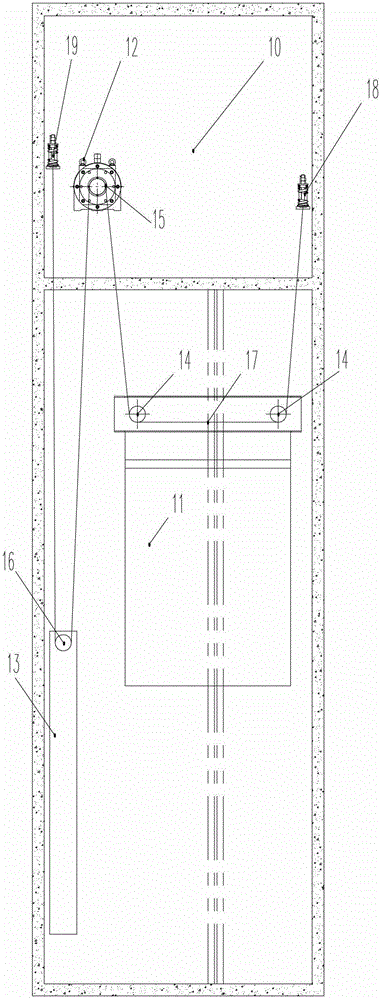
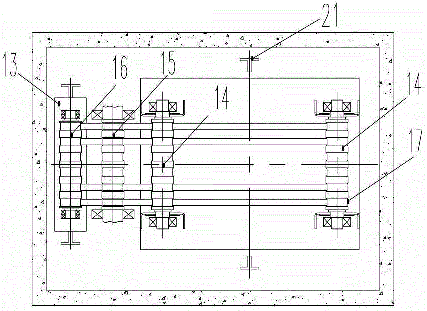
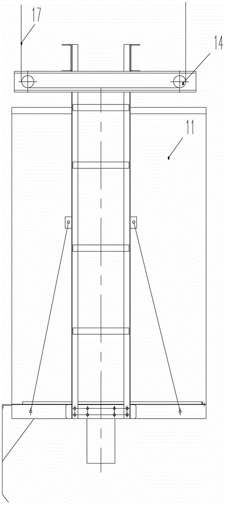
[0032] The present invention is an elevator traction system 10, such as figure 1 , including the guide pulleys 14, 15, 16 respectively located on the elevator car frame 11, the elevator main frame 12 and the counterweight 13, and the guide pulleys 14, 15, 16 are designed through improvement, and can be well used for flat type The guide of composite steel belt 17. Owing to adopting composite steel belt 17 as suspension and traction assembly, composite steel belt 17 is made up of multi-strand steel wire rope, and the diameter of steel wire rope can be less than 2mm, and then the diameter of guide pulley 14,15,16 can be 80mm, what present embodiment design is 95mm. The reduction of the diameter of the guide pulley enables the pulley and the load-bearing main shaft to be integrated. That means that the elevator car frame 11, the elevator main frame 12 and the counterweight 13 only need to assemble a pulley shaft (that is, the load-bearing main shaft), and the pulley shaft is pr...

Embodiment 2

[0041] Such as Figures 9 to 11 Shown is a layout plan with a machine room structure. There are two guide pulleys 20 transition between the guide pulley 15 of the elevator main engine 12 and the guide pulley 14 of the car frame 11, and the guide pulleys 14 are respectively placed on the top of the elevator car frame 11. The front and rear positions on the elevator can realize the simplification of the structure of the elevator system. Simultaneously, the composite steel belts 17 on the car side and the counterweight side can be placed vertically without offset angle, which greatly improves the running effect of the elevator.

[0042] Other structures are with embodiment 1.

Embodiment 3

[0044] Such as Figures 12 to 14 In order to be provided with the layout scheme of the machine room structure, there are two guide pulleys 20 transition between the guide pulley 15 of the elevator main frame 12 and the guide pulley 14 of the car frame 11, and the guide pulley 14 of the car frame 11 is placed on the car frame 11. The middle of the upper beam realizes the simplification of the structure of the elevator system. Simultaneously, the composite steel belts 17 on the car side and the counterweight side can be placed vertically without offset angle, which greatly improves the running effect of the elevator. In addition, a guide pulley 14 is also saved on the car frame 11, reducing the cost of the elevator.

[0045] Other structures are with embodiment 1.


PUM


Abstract

The invention discloses an elevator traction system. The elevator traction system comprises guiding pulleys which are arranged on an elevator lift car frame, an elevator main engine and a counterpoise, and composite steel belts which successively pass through the guiding pulleys, wherein the guiding pulleys are in an integrated structure of a pulley and a bearing main shaft, a guiding groove which is formed in a bearing main shaft is formed in the bearing main shaft, and the guiding groove is a groove with a flat base. On one hand, the elevator traction system solves the problems that the composite steel belts are in line deflection and load carrying capacity is uneven, on the other hand, the elevator traction system further solves the problems of inability to slip caused by an oversize friction coefficient by adopting the composite steel belts with a concave shape and a protruding shape and a rope sheave, so that the elevator traction system is authentically suitable for long term operation of the elevator. The elevator traction system has the advantages of being good in rigidity and intensity by adopting a wheel axle integrated structure, high in safety coefficient, compact in structure, capable of ensuring that an elevator device and an elevator complete machine structure are simplified, thereby reducing occupied space of the elevator device to an elevator well, and effectively saving well space.

Description

technical field [0001] The invention relates to the field of elevators, in particular to an elevator traction system. Background technique [0002] As a vertical transportation tool, elevators are closely related to modern social life. With the development of social economy and the acceleration of urbanization, there are more and more high-rise buildings, and high-rise buildings have become a city symbol, some even Become a landmark of the city. With the emergence of high-rise buildings and the development of social culture, the demand for elevators is becoming stronger and stronger, especially in today's aging society, the significance of elevators is even more important. Elevators all over the world are in operation every day, carrying a large number of people and logistics transportation. The role of elevators in buildings has become very important, and it is an indispensable part of modern social life. [0003] Traditional elevators mainly use steel wire ropes as the c...

Claims


Application Information

Patent Timeline
Patent Type & Authority Patents(China)
IPC IPC(8): B66B11/08
Inventor 贺云朗侯应浩
Owner GUANGZHOU GUANGRI ELEVATOR IND
Why Eureka
Try Eureka