Circular tube machining and clamping structure

A round tube and rotating column technology, applied in clamping devices, metal processing equipment, metal processing machinery parts, etc., can solve the problems of poor fixation and poor processing effect.

Inactive Publication Date: 2015-11-18
CHENGDU MATSUKAWA METAL MATERIALS
View PDF9 Cites 4 Cited by
  • Summary
  • Abstract
  • Description
  • Claims
  • Application Information

AI Technical Summary

Problems solved by technology

[0003] When the existing round tube is processed, it is often due to poor fixing, which leads to disadvantages such as poor processing effect

Method used


Image

  • Circular tube machining and clamping structure
  • Circular tube machining and clamping structure

Examples


Embodiment Construction

[0011] The present invention will be described in further detail below through specific implementation examples and in conjunction with the accompanying drawings.

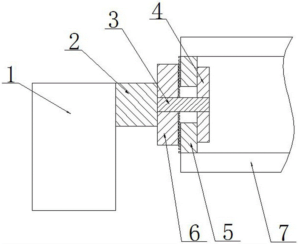
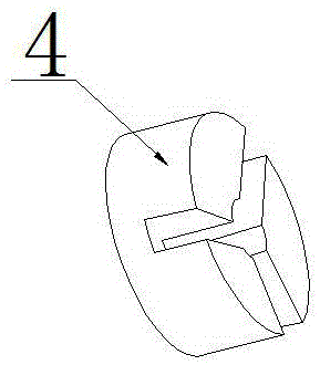
[0012] Figure 1-2 The clamping structure for round pipe processing provided by the present invention is shown, including a rotating shaft 2 , a mounting base 1 , a guide post 4 , a connecting shaft 3 , a rotating post 6 and a slider 5 . The mounting base 1 is provided with a rotating shaft 2, the end of the rotating shaft 2 is fixedly connected with a connecting shaft 3, the connecting shaft 3 is covered with a rotating column 6 and a guide column 4, and the rotating column 6 is mated with the outer surface of the connecting shaft 3, The guide column 4 is connected with the connecting shaft 3 through threads. One end surface of the rotation column 6 is matched with the end of the rotation axis 2, and the other end surface is provided with threads. A plurality of grooves are evenly distributed, and a slide block 5...


PUM


Abstract

The invention discloses a circular tube machining and clamping structure. The structure comprises an installation base, a rotary shaft is arranged on the installation base, and the tail end of the rotary shaft is fixedly connected with a connection shaft. The connection shaft is sleeved with a rotary column and a guide column. The outer circumference of the rotary column is connected with the outer circumference of the connection shaft in a matched mode. The guide column is connected with the connection shaft in a matched mode through threads. One end face of the rotary column is matched with the tail end of the rotary shaft, and the other end face of the rotary column is provided with a thread. The end face, corresponding to the threaded face of the rotary column, of the guide column is provided with a plurality of grooves which are evenly distributed. A slider is installed in the grooves in a matched mode. The slider is provided with a rack matched with the thread of the rotary column. Work efficiency is improved and cost is reduced through the clamping structure.

Description

technical field [0001] The invention relates to the field of round pipe processing equipment, in particular to a round pipe processing clamping structure. Background technique [0002] In the prior art, round pipes are often processed in various ways, such as welding flanges, drilling or cutting off, etc., so it is often necessary to fix round pipes. However, round pipes are different from ordinary workpieces and are difficult to fix and process. For example, when welding a flange, the connection between the flange and the round pipe is not firm before welding. It is usually necessary to place the flange flat on the workbench, and then place the round pipe vertically on the flange body to enhance welding. time stability. [0003] When the existing round pipe is processed, it is often due to poor fixing, which leads to disadvantages such as poor processing effect. Contents of the invention [0004] The object of the present invention is to provide a clamping structure for...

Claims


Application Information

Patent Timeline
Patent Type & Authority Applications(China)
IPC IPC(8): B23K37/053B23Q3/00
CPCB23K37/053B23Q3/062B23Q2703/10
Inventor 周建川
Owner CHENGDU MATSUKAWA METAL MATERIALS
Why Eureka
Try Eureka