Machining grinding machine and method for taper holes

A processing method and technology of tapered holes, which are applied in the processing and grinding machine of tapered holes and the field of processing, can solve the problems of low processing accuracy, inability to meet the technological requirements of the tapered hole 101 on the workpiece 1, and low grinding efficiency, so as to improve the forming process. The effect of machining efficiency and machining accuracy

Inactive Publication Date: 2015-11-18
自贡中兴耐磨新材料有限公司
View PDF7 Cites 7 Cited by
  • Summary
  • Abstract
  • Description
  • Claims
  • Application Information

AI Technical Summary

Problems solved by technology

[0004] One is, after the tapered hole 101 at one end of the workpiece 1 is processed, the grinding machine equipment needs to be stopped, and the tapered hole 101 at the other end of the workpiece 1 is ground after the workpiece 1 is turned over. When the angles are different, it is necessary to adjust the grinding machine headstock 3 and its feed rate, or use two tool grinders for grinding, and each tool grinder only grinds the tapered hole 101 on one end face of the workpiece 1. Therefore, the grinding process relatively low efficiency
[0005] Second, when the concentricity tolerance d of the taper holes 101 at both ends of the workpiece 1 is 0.05mm, the above-mentioned processing method cannot meet the technological requirements of the taper holes 101 on the workpiece 1 due to low machining accuracy and poor control during processing.

Method used


Image

  • Machining grinding machine and method for taper holes
  • Machining grinding machine and method for taper holes
  • Machining grinding machine and method for taper holes

Examples


Embodiment Construction

[0025] In order to make the object, technical solution and advantages of the invention clearer, the invention will be described in detail below in conjunction with the accompanying drawings and specific embodiments. It should be understood that the specific embodiments described here are intended to explain the present invention, not to limit the present invention.

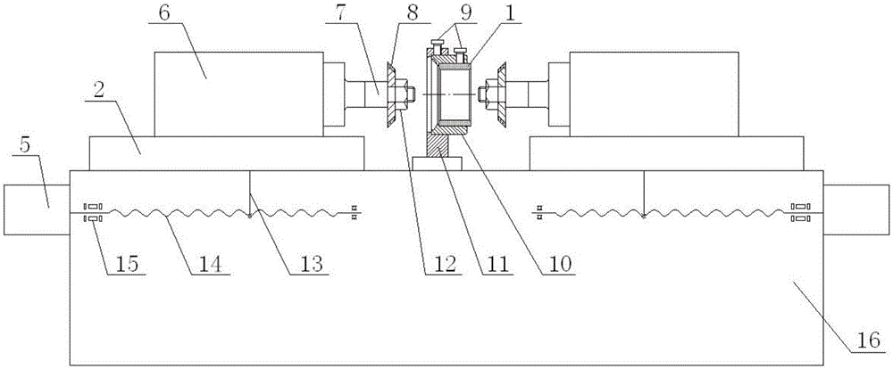
[0026] Such as image 3 A kind of processing grinding machine for tapered hole shown, comprises feed mechanism, grinding mechanism and clamping mechanism, described feed mechanism is provided with independent two groups, and each group of feed mechanism includes first motor 5, ball screw rod 14 and the transmission member 13 and the workbench 2, the first motor 5 and the ball screw 14 are all distributed on the two ends of the base 16 with the central axis of the grinder base 16 as the symmetrical axis, and at the same end of the base 16 In the feed mechanism, the output shaft of the first motor 5 and the ball sc...


PUM


Abstract

The invention provides a machining grinding machine and method for taper holes. The machining grinding machine comprises feeding mechanisms, grinding mechanisms and a clamping mechanism. Two sets of independent feeding mechanisms and two sets of independent grinding mechanisms are arranged. Each group of the grinding mechanism comprises second motors and a grinding wheel. The two second motors are fixedly connected with the corresponding independent group of the feeding mechanism. Output shafts of the two motors are fixedly connected with the grinding wheels respectively. The central axes of the two grinding wheels coincide with each other and the grinding faces of the two grinding wheels are erected opposite to each other. The grinding faces of the two grinding wheels are conical surfaces which are consistent with the tapers of the taper holes to be machined. The clamping mechanism is fixedly installed on a grinding machine base and located between the two grinding wheels. According to the machining grinding machine and method for the taper holes, a forming grinding mode is adopted; only one-time clamping operation of a workpiece needs to be conducted to achieve the synchronous machining of the taper holes in the two ends of the workpiece, so that the forming machining efficiency and the machining precision of the taper holes in the workpiece are improved greatly; moreover, the coaxiality of the taper holes in the two ends of the workpiece can reach up to 0.01 so that the coaxiality requirement of the taper holes in the two ends of the workpiece can be fully met.

Description

technical field [0001] The invention relates to the technical field of deep processing of taper holes on cemented carbide workpieces, in particular to a processing grinder and a processing method for taper holes. Background technique [0002] The deep processing of cemented carbide workpieces is carried out by grinding, and the deep processing of taper holes on the workpiece is no exception. For such as figure 1 The machining of the tapered holes 101 at both ends of the workpiece 1 shown is mostly performed by a tool grinder at present. Its specific processing method is as figure 2 As shown, during the grinding process, the workpiece 1 to be processed is clamped on the mandrel of the tool grinder, and the mandrel is clamped on the headstock 3 of the grinder. According to the taper requirements of the tapered hole 101, the grinding machine headstock 3 is deviated to a certain angle. When grinding, rely on the reciprocating motion of the grinding machine table 2, the rotar...

Claims


Application Information

Patent Timeline
Patent Type & Authority Applications(China)
IPC IPC(8): B24B5/14B24B27/00B24B47/20B24B41/06
CPCB24B5/14B24B27/0076B24B41/067B24B47/20
Inventor 钟健陈桂芳
Owner 自贡中兴耐磨新材料有限公司
Why Eureka
Try Eureka