Treatment method of settlement of high-speed railway roadbeds in soft-soil areas

A high-speed railway and roadbed technology, applied in the field of geotechnical engineering, can solve the problems of grouting amount, improper control of grouting pressure parameters, long time for grouting slurry to reach expected strength, adverse effects on roadbed structure and surrounding environment, etc. Subgrade settlement, low cost, and the effect of compensating settlement

Inactive Publication Date: 2015-11-18
TONGJI UNIV
View PDF5 Cites 10 Cited by
  • Summary
  • Abstract
  • Description
  • Claims
  • Application Information

AI Technical Summary

Problems solved by technology

Grouting reinforcement is to press the cement slurry under the high-speed railway foundation through flower tubes to improve the soil properties under the subgrade, but it takes a long time for the grouting slurry to reach the expected strength, and the grouting process may disturb the soft soil again, causing secondary settlement; the amount of grouting , grouting pressure and other parameters are not properly controlled, and the range of grout splitting and spreading in the soil is uncertain, causing adverse effects on the subgrade structure and surrounding environment
The reinforcement of jet grouting piles is to add jet grouting piles between the existing pile foundations to improve the bearing capacity of the roadbed foundation and control the development of roadbed diseases. However, the soil is disturbed greatly during the construction of jet grouting piles, which is very easy in soft soil areas. cause subgrade deformation and development

Method used


Image

  • Treatment method of settlement of high-speed railway roadbeds in soft-soil areas
  • Treatment method of settlement of high-speed railway roadbeds in soft-soil areas
  • Treatment method of settlement of high-speed railway roadbeds in soft-soil areas

Examples


Embodiment 1

[0032] The foundation of a certain high-speed railway was originally designed to be reinforced with grout-sprayed piles. The diameter of the grout-sprayed piles is 0.5m, the pile spacing is 1.3m, and the piles are arranged in an equilateral triangle. The pile length is 10-19.5m, and the reinforcement effect is not ideal. Now apply the present invention to carry out high-speed railway embankment settlement regulation, specifically comprise the following steps:

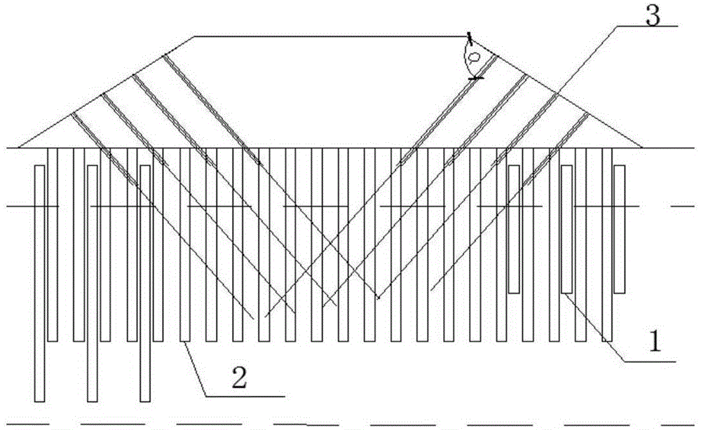
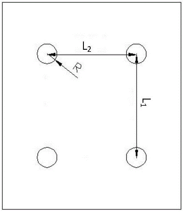
[0033] Step 1: The gap between the original pile foundation 2 grout sprayed piles that have been constructed at the toe of the subgrade slope is reinforced with rotary grouted pile 1. image 3 It is a schematic diagram of the rectangular arrangement of jet-grouting piles in the method for subgrade settlement improvement of high-speed railway in soft soil area according to the embodiment of the present invention, wherein the diameter of the jet-grouting piles is 0.5m, the pile length is 10.0-22.0m, and the horizontal dist...

Embodiment 2

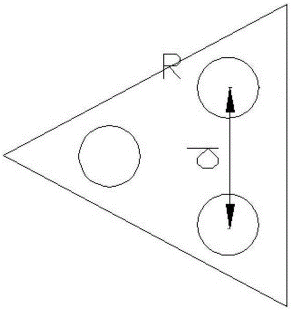
[0043] The difference from Example 1 is that the layout of the jet grouting piles adopts an equilateral triangle, such as figure 2 as shown, figure 2 It is a schematic diagram of the triangular arrangement of jet grouting piles in the method for subsidence control of high-speed railway subgrade in soft soil area according to the embodiment of the present invention. Now apply the present invention to carry out high-speed railway embankment settlement regulation, specifically comprise the following steps:

[0044] Step 1: The gap between the original pile foundation 2 grout sprayed piles that have been constructed at the toe of the subgrade slope is reinforced with rotary grouted pile 1. The pile diameter of the jet grouting pile is 0.5m, the radius R of the jet grouting pile is 0.25m, the length of the pile on the left side of the subgrade is 12.22m, and the length of the pile on the right side is 6.6m.

[0045]Step 2: After the rotary grouting pile reaches the design stren...

Embodiment 3

[0054] The difference from Embodiment 1 and Embodiment 2 is that the subgrade height of a certain section of a high-speed railway is low, and it is not suitable to arrange the grouting flower pipe 3 on the roadbed slope, so the grouting flower pipe 3 is arranged on the ground, such as Figure 4 as shown, Figure 4 It is a schematic diagram of the grouting flower tube on the ground in the method for subsidence control of high-speed railway subgrade in soft soil area according to the embodiment of the present invention. Now apply the present invention to carry out high-speed railway embankment settlement regulation, specifically comprise the following steps:

[0055] Step 1: The gap between the original pile foundation 2 that has been constructed at the slope toe of the subgrade is reinforced with rotary grouting pile 1. Among them, the diameter of the rotary grouting pile is 0.5m, the pile length is 10.0-22.0m, and the horizontal distance between piles is 2.6 m, 3 columns unde...


PUM


Abstract

The invention discloses a treatment method of the settlement of high-speed railway roadbeds in soft-soil areas. The treatment method comprises the following steps: firstly, reinforcing and strengthening the foundation of a high-speed railway roadbed; and then, reinforcing and strengthening the side slopes or the ground of the high-speed railway roadbed. In the step of reinforcing and strengthening the foundation of the high-speed railway roadbed, a plurality of rows of rotary jet grouting piles are constructed among original pile foundations at slope toes of a conventional high-speed railway roadbed for performing reinforcement and strengthening. In the step of reinforcing and strengthening the side slopes or the ground of the high-speed railway roadbed, grouting holes are formed in the side slopes or the ground of the conventional high-speed railway roadbed; perforated grouting pipe are inserted in the grouting holes; the seriflux is injected in the perforated grouting pipe, so that the reinforcement and the strengthening are completed. The treatment method of the settlement of high-speed railway roadbeds in soft-soil areas, provided by the invention is safe, reliable, scientific and reasonable, and low in cost. Through the adoption of the treatment method, the settlement of roadbeds is effectively controlled, and influence caused by the settlement of roadbeds on conventional roadbed structures and the surrounding environment is reduced.

Description

technical field [0001] The invention belongs to the technical field of geotechnical engineering, and relates to a method for regulating subgrade settlement of high-speed railways in soft soil areas. Background technique [0002] At present, my country's high-speed railway has entered a stage of rapid development. By the end of 2014, the operating mileage exceeded 16,000 kilometers, and the high-speed railway under construction and planning reached tens of thousands of kilometers. In the Yangtze River Delta, Pearl River Delta, and Beijing-Tianjin-Hebei areas where high-speed railways are densely distributed, high-speed railways are mostly built on soft soil strata, and the roadbed adopts pile-slab and pile-net composite structures to reduce settlement. However, affected by geological conditions and surrounding environments, soft soil Roadbed diseases of high-speed railways in the region still occur. If the subgrade settlement of high-speed railways is not effectively controll...

Claims


Application Information

Patent Timeline
Patent Type & Authority Applications(China)
IPC IPC(8): E01C3/00E02D17/20
Inventor 周顺华肖军华张继鹏程茜宫全美
Owner TONGJI UNIV
Why Eureka
Try Eureka