
Built-in continuous oil tube well completion tube column and construction method thereof

A built-in, tubing technology, used in earth-moving drilling, wellbore/well components, sealing/packing, etc., can solve problems such as lack of reliable plugging devices, potential safety hazards, affecting gas well production, etc., and achieve convenient and safe start-up. The effect of reducing wellbore fluid accumulation and prolonging production time

Active Publication Date: 2015-11-18
CHINA PETROLEUM & CHEM CORP +1
View PDF7 Cites 3 Cited by
  • Summary
  • Abstract
  • Description
  • Claims
  • Application Information

AI Technical Summary

Problems solved by technology

[0005] (1) After the plug connected to the bottom of the coiled tubing is opened to establish a production channel, the opening core cannot be fixed, and it is easy to go back up under the impact of the downhole fluid and block the coiled tubing again, affecting the production of the gas well; When coiled tubing is used to produce strings, there is no reliable plugging device, and real underpressure operation cannot be realized.
[0006] (2) When the coiled tubing is completed, the hanger used to fix the coiled tubing is installed between the No. 1 valve at the wellhead and the gas tree. After the coiled tubing is completed, it passes through the No. 1 valve. The No. 1 valve cannot be closed, and the downhole high-pressure gas flow cannot be quickly blocked, which poses certain safety hazards

Method used


Image

  • Built-in continuous oil tube well completion tube column and construction method thereof
  • Built-in continuous oil tube well completion tube column and construction method thereof
  • Built-in continuous oil tube well completion tube column and construction method thereof

Examples


Embodiment Construction

[0043] The present invention will be further described below in conjunction with accompanying drawing.

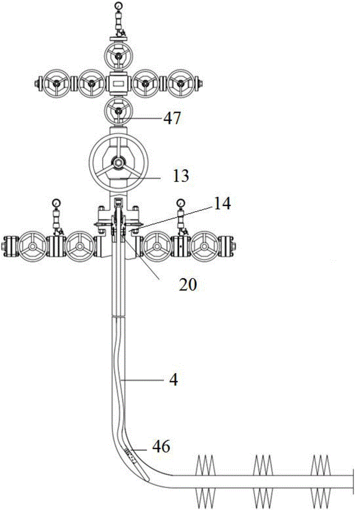
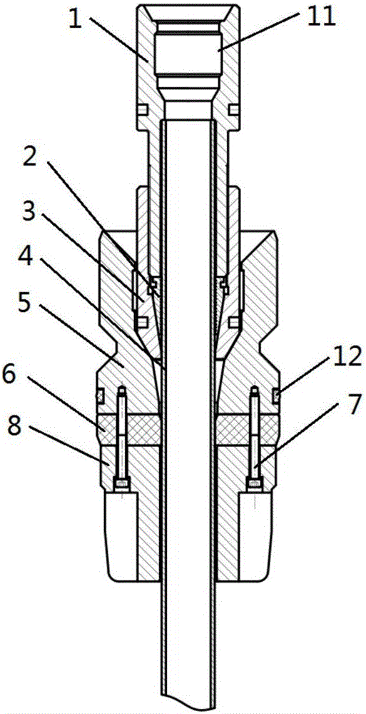
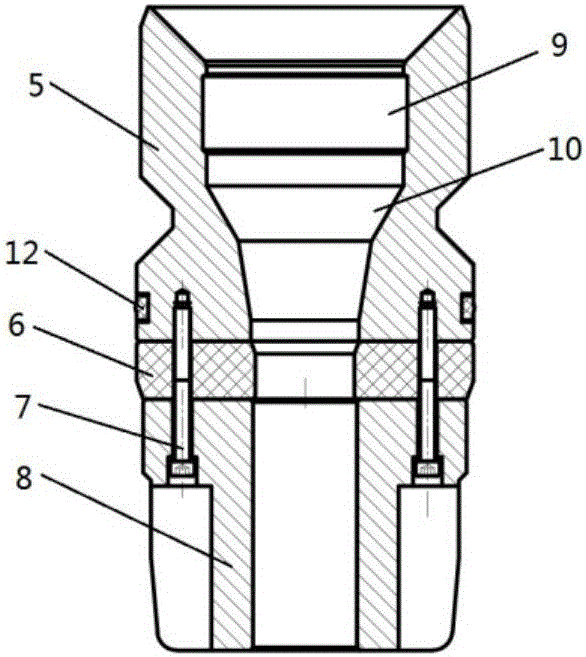
[0044] Such as figure 1 As shown, this embodiment provides a built-in coiled tubing completion production string, which includes a built-in hanger 20, a coiled tubing 4, a plug and a plugging rod, and the upper end of the coiled tubing 4 is connected to the built-in hanger 20 sealing configuration, and hang on the built-in hanger, the built-in hanger is installed in the wellhead tubing head 14, the wellhead No. 1 valve 13 is installed above the wellhead tubing head 14, the bottom of the coiled tubing 4 Connected with the plug, when the string is lowered, the plug plugs the coiled tubing, and the plug is hydraulically opened to realize completion production, and the plug rod is used to cooperate with the plug to plug the coiled tubing for the second time when the completion string is lifted.

[0045] Such as Figure 2-5 As described above, the built-in hanger includes a lo...


PUM


Abstract

The invention discloses a built-in continuous oil tube well completion tube column and a construction method thereof. The tube column comprises a built-in hanger, a continuous oil tube, a blocking device and a blocking rod. The upper end of the continuous oil tube is configured with the built-in hanger in a sealed mode and hung through the built-in hanger. The built-in hanger is arranged in a wellhead oil tube. The bottom of the continuous oil tube is connected with the blocking device. The blocking rod is used for being matched with the blocking device to secondarily seal the continuous oil tube when the well completion tube column is withdrawn. According to the built-in continuous oil tube well completion tube column and the construction method thereof, the built-in hanger at the upper end of the tube column is arranged in a wellhead oil tube head; when the pressure of the tube column under a well is abnormal, downhole airflow can be blocked off quickly by closing a first valve at a wellhead, and safety accidents are avoided. The tube column can achieve gas well extraction with liquid through the blocking function of the blocking device at the bottom of the tube column and the blocking rod matched with the blocking device, accumulated liquid in a pitshaft can be effectively relieved, return pressure at the shaft bottom is lowered, and the gas well extraction time is prolonged.

Description

technical field [0001] The invention relates to the field of petroleum and natural gas, in particular to a built-in coiled tubing well completion production string and a construction method thereof, which is applied to gas reservoir pressure drop, stratum water discharge leading to fluid accumulation at the bottom of the well; back pressure at the bottom of the well increases, gas wells Exploitation of low-yield and low-efficiency gas fields with rapidly declining production and other related fields. Background technique [0002] During the development of gas reservoirs, as the formation pressure decreases, the gas flow rate decreases, and the liquid-carrying capacity of gas wells gradually deteriorates. Fluid accumulation began to appear in the wellbore, and the back pressure at the bottom of the well continued to increase, resulting in a decrease in the production pressure difference of the gas well and a sharp drop in production. How to improve the liquid-carrying capaci...

Claims


Application Information

Patent Timeline
IPC IPC(8): E21B23/01E21B33/03E21B33/12
Inventor 王大江费成俊刘军夏续波徐冠军孙志扬喻建川郭玉娟刘星赵昆
Owner CHINA PETROLEUM & CHEM CORP
Learn More