Charging valve

A liquid filling valve and valve body technology, which is applied in the direction of lifting valve, valve detail, control valve, etc., can solve the problems of uneven impact force of the valve core, difficult control of the valve core, large volume of the filling valve, etc., and achieve a simplified structure , high concentricity and simple valve core structure

Active Publication Date: 2015-11-18
ZHONGSHAN WENTIANCHANG HYDRAULIC MACHINERY
View PDF6 Cites 3 Cited by
  • Summary
  • Abstract
  • Description
  • Claims
  • Application Information

AI Technical Summary

Problems solved by technology

At present, the oil outlet hole of the liquid filling valve on the market is generally set on the side of the valve body and its number is only one, which will cause uneven impact force of the oil on the valve core when the oil enters, and the accuracy of the valve core will decrease over time, and even May need to be replaced frequently, and may also result in low oil intake and difficult spool control
In addition, the inner cavity of the filling valve installed on the market is generally composed of two parts, which will result in low concentricity and low pressure resistance, and will also lead to a more complex structure, difficult control and a larger overall volume of the filling valve.

Method used


Image

  • Charging valve
  • Charging valve
  • Charging valve

Examples


Embodiment Construction

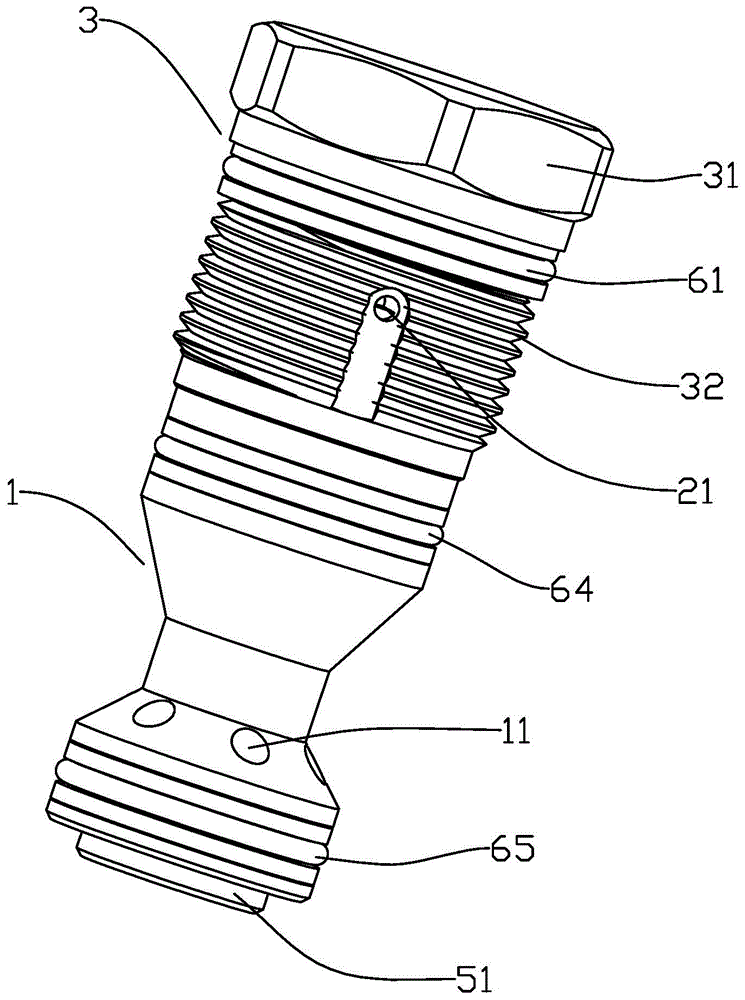
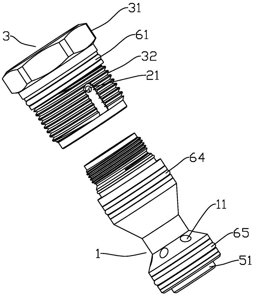
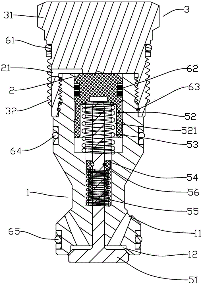
[0024] refer to Figures 1 to 3 , the first embodiment of the present invention, a liquid filling valve, including an integral valve body 1 and a valve core longitudinally slidably arranged in the inner cavity of the valve body 1, and the valve core is encapsulated by a cover In the inner chamber of the valve body 1, the valve body 1 is provided with at least one liquid inlet 11 and at least one liquid outlet 12 communicated with the liquid inlet 11, and the shape of the upper part of the valve core is consistent with that of the inner chamber of the valve body 1. The shape is matched, and its outer wall is close to the inner wall of the valve body 1 so as to isolate part of the inner cavity of the upper part of the valve body 1 into a control chamber 2, and the cover or the outer wall of the valve body 1 is provided with at least A control port 21 , the fluid entering and leaving the control chamber 2 through the control port 21 can push the valve core to move longitudinally ...


PUM


Abstract

The invention relates to a charging valve. The charging valve comprises an integral valve body and a valve element which is longitudinally arranged in an inner cavity of the valve body in a sliding mode. The valve element is packaged in the inner cavity of the valve body through a sealing cap. The valve body is provided with at least one liquid inlet and at least one liquid outlet communicated with the liquid inlet. The shape of the upper portion of the valve element is matched with that of the inner cavity of the valve body. The outer wall of the valve element is closely attached to the inner wall of the valve body, so that part of the inner cavity on the upper portion of the valve body is isolated to form a control cavity. The outer wall of the sealing cap or the outer wall of the valve body is provided with at least one control port communicated with the control cavity. Fluid entering and getting out of the control cavity from the control port can push the valve element to longitudinally move, so that connection and disconnection between the liquid inlet and the liquid outlet are controlled. The valve body is of an integral structure, concentricity is high, and the charging valve is high in pressure resistance, small in size, easy to produce, easy in function implementation, convenient to operate and install and high in universality.

Description

technical field [0001] The invention relates to a filling valve. Background technique [0002] The filling valve generally includes a valve body and a valve core, which acts as a one-way check between the hydraulic oil tank and the hydraulic cylinder, and the oil outlet hole of the valve body is connected with the oil inlet hole of the hydraulic cylinder. At present, the oil outlet hole of the liquid filling valve on the market is generally set on the side of the valve body and its number is only one, which will cause uneven impact force of the oil on the valve core when the oil enters, and the accuracy of the valve core will decrease over time, and even Frequent replacement may be required, which may also result in less oil intake and difficult spool control. In addition, the inner cavity of the spool installed in the filling valve currently on the market is generally composed of two parts, which will result in low concentricity and low pressure resistance, and will also l...

Claims


Application Information

Patent Timeline
Patent Type & Authority Applications(China)
IPC IPC(8): F16K15/02F16K27/02F16K1/36F16K1/46
CPCF16K1/36F16K1/46F16K15/025F16K27/0209
Inventor 文杰
Owner ZHONGSHAN WENTIANCHANG HYDRAULIC MACHINERY
Why Eureka
Try Eureka