Novel efficient intelligent environment-friendly ecological navigation mark

An environmentally friendly and efficient technology, applied in the field of navigation marks, can solve the problems of high unit cost, high energy consumption, and high cost, and achieve the effects of reducing the number of manual maintenance, low cost, and high economy

Inactive Publication Date: 2015-11-18
WUHAN UNIV OF TECH
4 Cites 5 Cited by

AI-Extracted Technical Summary

Problems solved by technology

Among them, photovoltaic power generation is the most common and relatively mature form of solar power generation. The main form of photovoltaic power generation is solar panels. Solar panels are very clean when used, but the production process cons...

Method used

One side of the eyeglass surface of Fresnel lens is smooth surface, and the other side has engraved concentric circles from small to large, and its texture is designed according to the interference of light and the requirements of relative sensitivity and receiving angle, and has Very good light concentrating effect, the Fresnel concentrating lens is inlaid on the upper surface of the thermoelectric power generation m...

Abstract

The invention relates to a navigation mark, in particular to a novel efficient intelligent environment-friendly ecological navigation mark. The novel efficient intelligent environment-friendly ecological navigation mark is characterized in that a navigation mark body, a rotating control device, a bird repelling device, an illumination lamp and a power generation device are included; the navigation mark body comprises a rotatable support, a rotating device and a base, and the rotatable support is arranged on the base through the rotating device; the rotating deice rotates to drive the rotatable support to rotate and is controlled by the rotating control device; the bird repelling device comprises a sound projector, an infrared detector and a sound timing controller, and the sound projector and the infrared detector are fixed to the top of the rotatable support; the illumination lamp is arranged on the upper portion of the rotatable support; the power generation device comprises solar thermoelectric generators, solar trackers and a storage battery. According to the navigation mark, solar energy can be effectively utilized, no pollution exists, and cost is low; the bird repelling device is additionally arranged so that the navigation mark can be effectively kept clean, and the frequency of manual maintenance is greatly reduced.

Application Domain

Waterborne vesselsElectrical apparatus +6

Technology Topic

PhysicsSolar tracker +5

Image

  • Novel efficient intelligent environment-friendly ecological navigation mark
  • Novel efficient intelligent environment-friendly ecological navigation mark
  • Novel efficient intelligent environment-friendly ecological navigation mark

Examples

  • Experimental program(1)

Example Embodiment

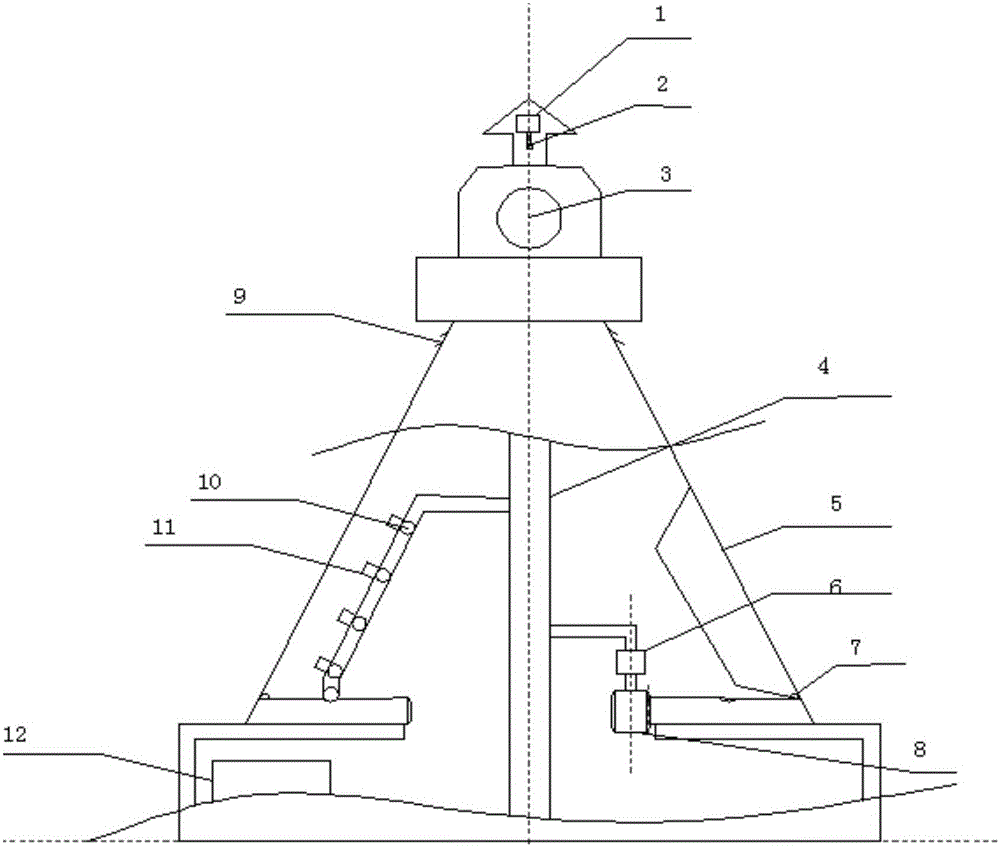
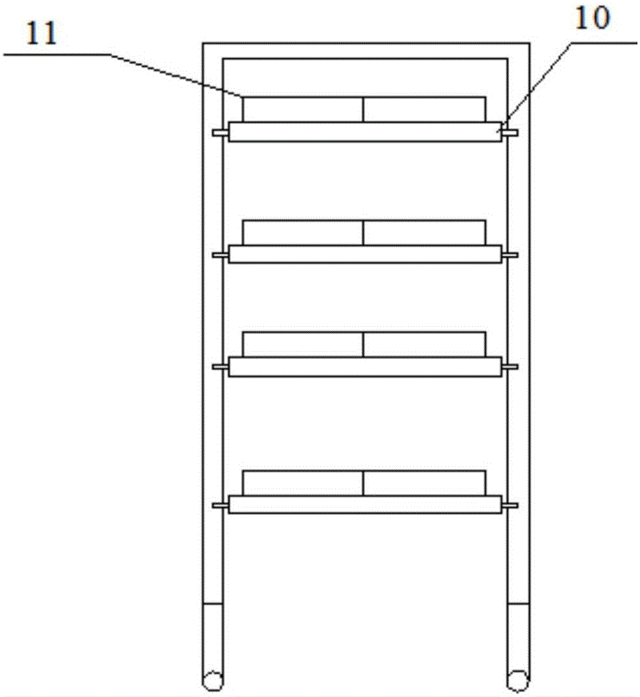
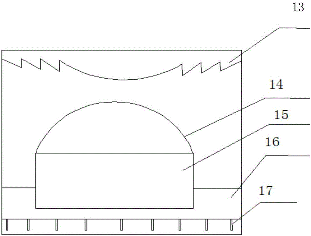
[0031] Such as Figure 1-6 As shown, a new type of high-efficiency, intelligent and environmentally friendly ecological navigation mark is characterized by including a navigation mark body, a rotation control device, a bird repellent device, a lighting lamp 3, and a power generation device;
[0032] The navigation mark body includes a rotatable bracket 4, a rotating device, and a base. The rotatable bracket 4 is installed on the base through the rotating device (the rotating device rotates to drive the rotatable bracket 4 to rotate, and the rotating device is controlled by the rotation control device);
[0033] The rotation control device includes a photoresistor 7 and a motor controller 6. A photoresistor 7 is installed on both sides of the rotatable support (hollow) 4, and the photoresistor 7 is connected to the motor controller 6, and the control terminal of the motor controller 6 Connected to the motor 8 of the rotating device; due to the continuous change of the angle of sunlight, the currents generated on the photoresistors on both sides of the navigation mark are different, so the motor controller 6 controls the motor 8 to drive the entire power generation device to rotate toward the sun to a fixed position. On the reverse side, the motor drives the power generation device to rotate to make full use of the daylight. When the current on both sides is not much different and is lower than the set value, the motor remains stationary, realizing intelligent control;
[0034] The bird repellent device includes a sound transmitter 1, an infrared detector 2, and a sound timing controller. The sound transmitter 1 and the infrared detector 2 are respectively fixed on the top of the rotatable bracket 4, the sound transmitter 1, and the infrared detector 2. They are electrically connected to the control terminal of the sound timing controller, and the power input terminal of the sound timing controller is connected to the battery (including the inverter) 12 (the battery 12 provides power); the bird repellent device on the top of the navigation mark and the infrared detector 2 The detection range is small. When a bird appears inside, the sound transmitter 1 starts to work. Set a working time of 5s to maintain a better bird repellent effect. In order to prevent birds from adapting to these sounds, the sound transmitter is set to Randomly play some sounds with better bird repellent function;
[0035] The illuminating lamp 3 is fixedly installed on the upper part of the rotatable bracket 4. The illuminating lamp 3 is electrically connected to the control end of the lighting control circuit by a wire, and the power input end of the lighting control circuit is connected to the battery (including the inverter) 12 (battery 12 Provide lighting power);
[0036] The power generation device includes a solar thermoelectric generator 11, a solar tracker 10, and a battery 12; the solar thermoelectric generator 11 is fixed on the solar tracker 10, the solar tracker 10 is fixed on the rotatable support 4, and the solar thermoelectric generator 11 The power output terminal of is connected to the battery 12 (the solar thermoelectric generator provides power to the battery 12), and the solar tracker 10 is electrically connected to the battery 12 (the battery 12 provides power to the solar tracker 10).
[0037] The solar thermoelectric generator (or solar thermal thermoelectric generator) 11 includes a body (or a bracket), a Fresnel condenser lens 13, a thermoelectric power module 15, a heat collector 14 and an independent water tank (small water tank). 16. Metal fins 17, Fresnel condenser lens 13 is located at the top of the body, water tank 16 is located at the bottom of the body 5cm, metal fins 17 are evenly distributed at the bottom of the water tank to enhance heat dissipation, and the cold end of the thermoelectric power generation module 15 is closely attached to On the water tank, a heat collector 14 is installed on the upper part of the thermoelectric power generation module 15 as a hot end.
[0038] The lens surface of the Fresnel lens is glossy on one side, and concentric circles from small to large are recorded on the other side. Its texture is designed according to the interference of light and the requirements of relative sensitivity and receiving angle. For concentrating function, Fresnel condensing lens is inlaid on the upper surface of the thermoelectric power module to condense sunlight. The solar thermoelectric generator uses a Fresnel lens to gather sunlight. The concentrated sunlight is concentrated on a heat collector. The heat collector generates high temperature as the hot end of the thermoelectric power generation module, and the cold end of the thermoelectric power generation is a cooling water tank. The generator generates electricity through temperature difference.
[0039] The rotating device includes a motor 8, a worm wheel, and a worm. The motor 8 is fixed on the base. The output shaft of the motor 8 is connected with a worm. The worm is meshed with the worm wheel. The lower outside of the rotatable bracket 4 is fixed with a worm wheel (the motor 8 works). , Drives the rotatable support to rotate, and the motor 8 is controlled by two photoresistors 7).
[0040] The lower end of the rotatable bracket (hollow) 4 is provided with a pulley (or slider), and the pulley (or slider) is located in a slideway on the base (the slideway is circular, and the rotatable bracket can slide around Road rotation).
[0041] The rotatable bracket 4 is provided with a shell, and the shell outside the solar thermoelectric generator 11 has an opening. The shell is provided with a transparent mirror 5, and the photosensitive resistor 7 is located at the transparent mirror 5. The upper part is provided with heat dissipation holes 9.
[0042] There are photoresistors on both sides of the navigation mark. From morning to noon, the sun shines on one photoresistor, causing the photoresistors on both sides to pass unequal amounts of current. At this time, the controller receives the current signal and controls the motor to rotate towards the sun. After noon, the sun shines on the photoresistor on the other side to produce a corresponding current change. The controller controls the motor to drive the power generator to turn to the sunny side. When it is rainy or when there is no sunlight, the current of the photoresistor on both sides does not change. If it is greater than the set value, the motor will not rotate and keep the original position. The bird repellent device located on the navigation mark, through the detection of infrared rays, the sound transmitter maintains a sound of about 5s to drive away the birds. Due to the small detection range, the birds are driven away without affecting the survival of the birds.

PUM

no PUM

Description & Claims & Application Information

We can also present the details of the Description, Claims and Application information to help users get a comprehensive understanding of the technical details of the patent, such as background art, summary of invention, brief description of drawings, description of embodiments, and other original content. On the other hand, users can also determine the specific scope of protection of the technology through the list of claims; as well as understand the changes in the life cycle of the technology with the presentation of the patent timeline. Login to view more.

Similar technology patents

Stable easy-separation nanoscale iron ball, preparation method thereof and application thereof

InactiveCN102600777AOvercoming easy oxidation and difficult separationImprove utilization efficiency
Owner:TIANJIN NORMAL UNIVERSITY

Multifunctional membrane aeration artificial wetland sewage treatment system

InactiveCN103864217AImprove utilization efficiencyEnhanced gas mass transfer performance
Owner:CHANGAN UNIV

Classification and recommendation of technical efficacy words

  • Improve utilization efficiency

Charging method for mobile robot in wireless charging sensor network system

ActiveCN105896672AImprove utilization efficiencyNetwork Energy Consumption Balance
Owner:HOHAI UNIV CHANGZHOU

Solar cell packaging adhesive film with high light conversion efficiency

ActiveCN104927686AImprove utilization efficiencygood light stability
Owner:HANGZHOU FIRST APPLIED MATERIAL CO LTD
Why Eureka
Try Eureka