Fluorescent lamp tube replacing device

A technology for fluorescent lamps and lamp tubes, applied to lighting devices, components of lighting devices, light source fixing, etc., can solve problems such as electric shock hazards and falling, and achieve the effects of not easy to fall off, light in weight, and not easy to damage

Inactive Publication Date: 2015-11-18
SHENYANG INSTITUTE OF CHEMICAL TECHNOLOGY
View PDF6 Cites 6 Cited by
  • Summary
  • Abstract
  • Description
  • Claims
  • Application Information

AI Technical Summary

Problems solved by technology

[0002] In daily life, people use more fluorescent lamps to replace fluorescent lamps. When replacing fluorescent lamps, because the lamp tube is located very high, it is necessary to climb a ladder or step on a stool to replace it, which can easily cause a fall from a high place or cause an electric shock hazard. invented a device to help people change light tubes

Method used


Image

  • Fluorescent lamp tube replacing device

Examples


Embodiment Construction

[0012] The present invention will be described in detail below in conjunction with examples.

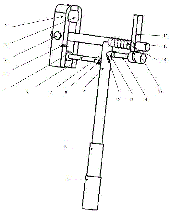
[0013] The device of the present invention consists of lamp claw 1, lamp claw 2, guide rod 3, spring 4, cam 5, left support arm 6, eccentric wheel 7, locking traction wire 8, hollow pole 9, adjustment screw 10, adjustment nut 11 , Pressing plate traction line 12, eccentric wheel 13, right support arm 14, slotted cylindrical cam 15, spring 16, guide rod 17, end pressing plate 18 forms. The fluorescent lamp replacement device controls the locking or loosening of the lamp claws through the locking traction line, and the other pressure plate traction line controls the end pressure plate so that the lamp tube is pressed to one end, and then one end is released. At this time, it can be removed or installed smoothly. Fluorescent tubes. Lamp clamping mechanism: two claw lamps 1 and 2 are located on a guide rod 3, spring 4 is connected to claw lamps 1 and 2 to keep the two claws in a half-cl...


PUM


Abstract

The invention provides a fluorescent lamp tube replacing device which comprises two lamp claws, two guide rods, two springs, a cam, a left supporting arm, two eccentric wheels, a locking pull wire, a hollow strut, an adjustment screw, an adjustment nut, a pressing plate pull wire, a right supporting arm, a slotted cylindrical cam and an end pressing plate. The pull wire is connected with the lamp claws, and the pressing plate pull wire is connected with the end pressing plate. A lamp tube clamping mechanism is characterized in that the two clamp claws are located on one guide rod, the springs are connected to the lamp claws to enable the two clamp claws to be kept in a semi-enclasping state, the cam is located between the clamp claws, and the left supporting arm is connected with the strut. The problems that people need to dismount or mount a fluorescent lamp by climbing a ladder or stepping on a stool due to the fact that the position of a lamp tube is too high, and people fall off from the high position or have an electric shock hazard easily are solved. Most of all, the fluorescent lamp tube replacing device provides a convenient and reliable tool used for mounting or dismounting the lamp tube for the old, the children, short people and people with acrophobia.

Description

technical field [0001] The invention relates to a daily fluorescent lamp device, in particular to a fluorescent lamp tube replacement device. Background technique [0002] In daily life, people use more fluorescent lamps to replace fluorescent lamps. When replacing fluorescent lamps, because the lamp tube is located very high, it is necessary to climb a ladder or step on a stool to replace it, which can easily cause a fall from a high place or cause an electric shock hazard. A device was invented to help people change lamp tubes. Contents of the invention [0003] The purpose of the present invention is to provide a fluorescent lamp tube replacement device. When people install and replace fluorescent lamps, this device can avoid the need to climb ladders or step on stools to disassemble and install due to the high position of the fluorescent lamps. Falling, or the risk of electric shock, especially provide a convenient and reliable tool for the elderly, children, short pe...

Claims


Application Information

Patent Timeline
IPC IPC(8): F21V19/04
CPCF21V19/04
Inventor 李铁军赵艳春王丹仲海鹏
Owner SHENYANG INSTITUTE OF CHEMICAL TECHNOLOGY
Why Eureka
Try Eureka