
A temperature-measuring microwave oven and its working control method

A technology for microwave ovens and control devices, which is applied to household stoves/stoves, household heating, lighting and heating equipment, etc. It can solve problems such as microwave leakage and reliability impact, and achieve the effect of preventing excessive operating temperature and ensuring reliability

Active Publication Date: 2017-10-24
NINGBO FOTILE KITCHEN WARE CO LTD
View PDF7 Cites 0 Cited by
  • Summary
  • Abstract
  • Description
  • Claims
  • Application Information

AI Technical Summary

Problems solved by technology

[0004] For the technology of real-time detection of the temperature of the heated food in the microwave oven, in order to ensure safety and stability, a non-contact temperature detection device is often used, and the detection probe of the non-contact temperature detection device is often installed in the microwave oven. Inside or outside the ring wall of the heating cavity, and aligned with the flat plate of the object to be heated in the microwave heating cavity, then when the non-contact temperature detection device is working in the microwave oven, its temperature will increase with the increase of the temperature of the microwave heating cavity, and the surface It will also condense the oil fume and water vapor generated in the microwave heating chamber, which will greatly affect the reliability of its work; in addition, when installing the detection probe, it is often necessary to open a hole on the back plate of the microwave chamber, and this opening will not be used in actual use. , will cause microwave leakage

Method used


Image

  • A temperature-measuring microwave oven and its working control method
  • A temperature-measuring microwave oven and its working control method
  • A temperature-measuring microwave oven and its working control method

Examples


Embodiment Construction

[0024] The present invention will be further described in detail below in conjunction with the accompanying drawings and embodiments.

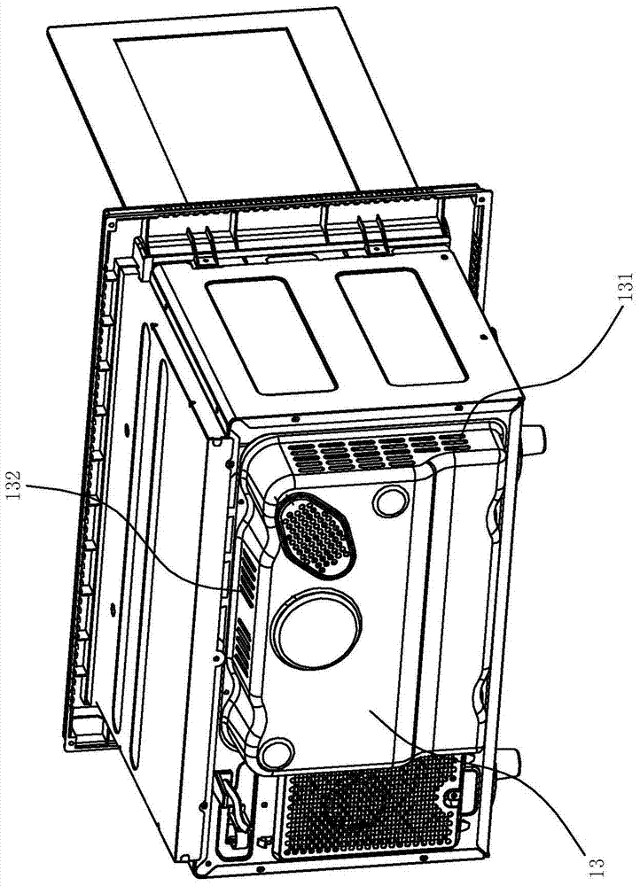
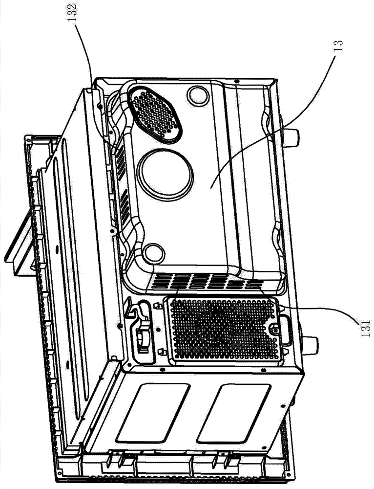
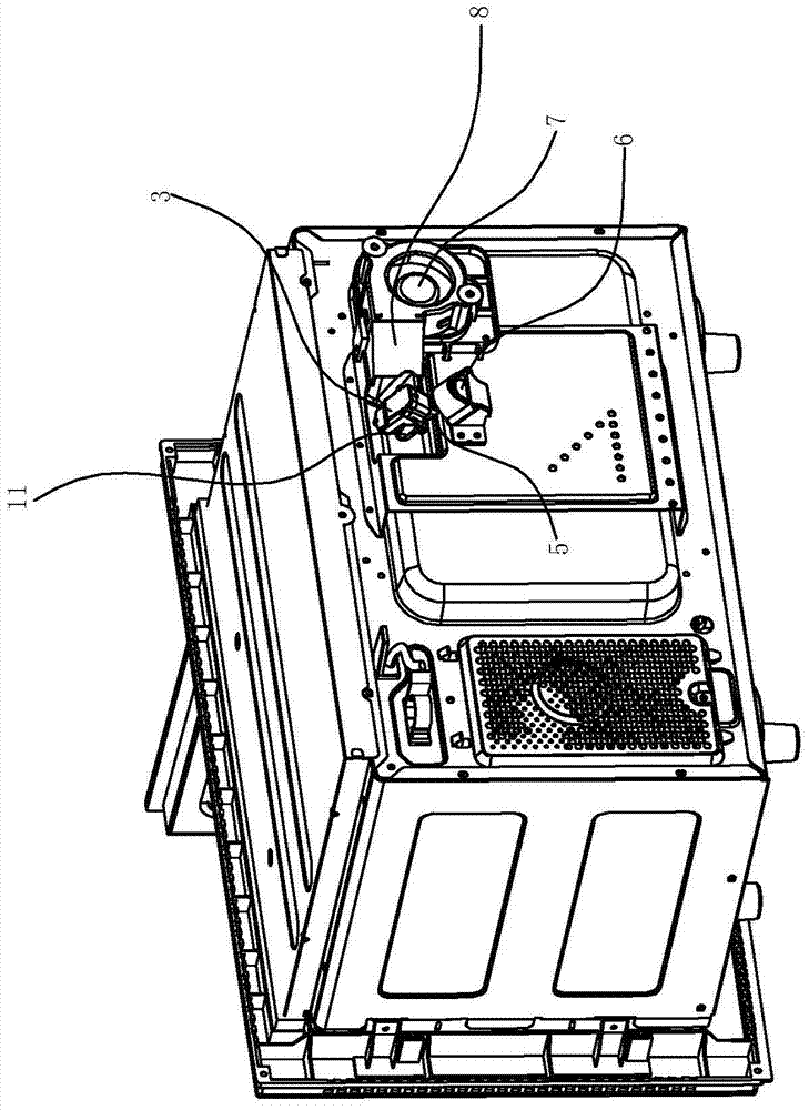
[0025] Such as Figure 1~6 The shown temperature-measuring microwave oven includes a microwave heating cavity 1 for placing the object to be heated, and a flat plate 2 for placing the object to be heated in the microwave heating cavity for generating microwaves to heat the heated object in the microwave heating cavity. A magnetron heating tube (not shown in the figure) for heating the object, and a non-contact temperature detection device 3 for detecting the temperature of the object to be heated. The upper rear part of the microwave heating chamber 1 is provided with an opening near the upper part. 11. The shape of the opening is U-shaped, and the periphery of the opening has a flange 12 facing out of the microwave heating chamber. The height of the flange 12 is 2 mm to 5 mm. The shape of the opening can also be replaced by an ellipse, so Th...


PUM


Abstract

The invention relates to a temperature-measuring microwave oven and a working control method thereof, wherein the temperature-measuring microwave oven includes a microwave heating chamber for placing an object to be heated, and a non-contact temperature detection device for detecting the temperature of the object to be heated. There is a flat plate for placing the object to be heated in the heating chamber, and an opening is arranged on the ring wall of the microwave heating chamber, and the non-contact temperature detection device includes a detection probe, which is facing the opening or is located in the Inside the opening, it is characterized in that: a cooling fan capable of cooling down the non-contact temperature detection device is arranged on the side of the non-contact temperature detection device. Compared with the prior art, the heat dissipation fan in the present invention can prevent the working temperature of the non-contact temperature detection device from being too high, and can also blow away the oil fume and water vapor near the non-contact temperature detection device when the microwave oven is heating food, so that the non-contact temperature detection device can be heated. The surface of the drive motor of the contact temperature detection device is not prone to condensation of oily smoke and water vapor during long-term use.

Description

technical field [0001] The invention relates to a temperature-measuring microwave oven and a working control method thereof. Background technique [0002] A microwave oven is a device in which a magnetron generates microwaves after the power is turned on, and irradiates these microwaves on food and other heated objects to cook food. Microwave ovens use the principle that the molecules of food to be cooked are subjected to alternating electromagnetic fields in the cavity of the microwave oven to generate high-frequency motion, and the principle of high-speed and intense friction between molecules generates heat to heat food. When the microwave oven is working, avoid the leakage of the generated microwaves, because the human body can also absorb microwaves. Once the human body is exposed to microwave radiation, it will have adverse effects on health. [0003] In recent years, people have paid more and more attention to healthy eating. As a microwave oven with high daily use ...

Claims


Application Information

Patent Timeline
Patent Type & Authority Patents(China)
IPC IPC(8): F24C7/02F24C7/08
Inventor 付远华夏保清余科帆郑伟曹骥茅忠群诸永定
Owner NINGBO FOTILE KITCHEN WARE CO LTD
Learn More