
Cold atom interferometry principle-based inertia measuring device

A technology of inertial measurement and inertial measurement unit, which is applied in directions such as navigation through speed/acceleration measurement, and can solve the problems that inertial parameters cannot be output and used at the same time, and cannot be used as an inertial measurement unit.

Active Publication Date: 2015-11-18
NO 717 INST CHINA MARINE HEAVY IND GRP
View PDF5 Cites 24 Cited by
  • Summary
  • Abstract
  • Description
  • Claims
  • Application Information

AI Technical Summary

Problems solved by technology

In the traditional atomic interference inertial measurement scheme, most of them can only measure the angular rate information and acceleration information in one direction, which cannot be used as an inertial measurement unit
In 2006, B.canel of the Paris Observatory realized a six-axis inertial sensor based on the atomic interference effect. Using different Raman light configurations, the time-sharing measurement of acceleration and rotation rate in three orthogonal directions can be realized. Because of this The six inertial parameters cannot be output at the same time, so it does not meet the requirements of inertial measurement equipment

Method used

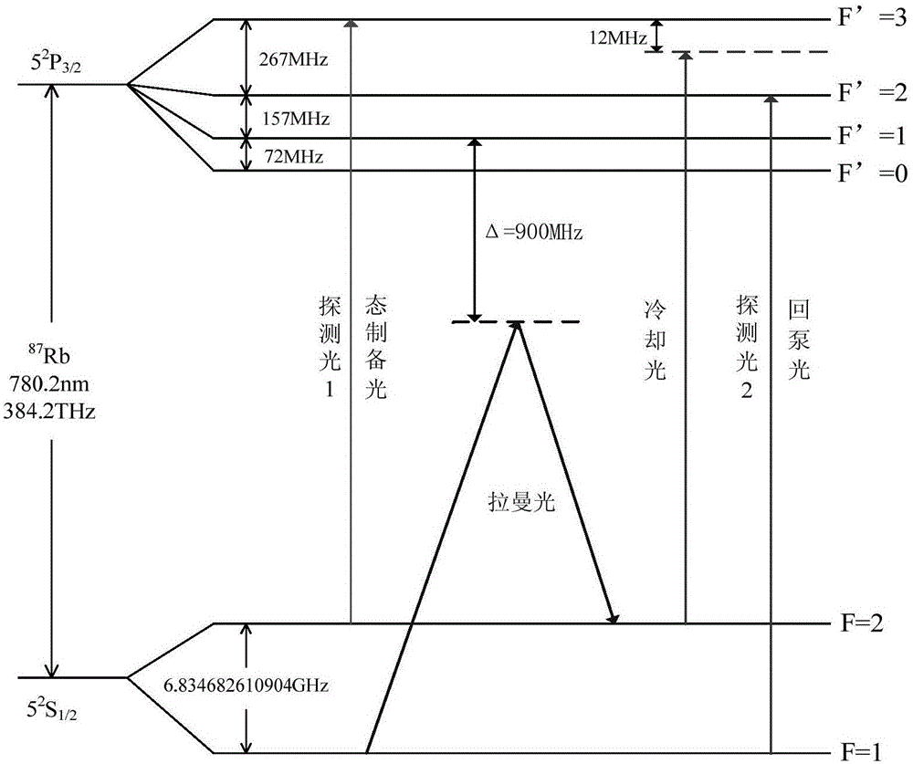
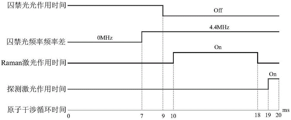

Image

  • Cold atom interferometry principle-based inertia measuring device
  • Cold atom interferometry principle-based inertia measuring device
  • Cold atom interferometry principle-based inertia measuring device

Examples


Embodiment Construction

[0041] The specific implementation method of the inertial measurement device based on cold atoms of the present invention will be described below with reference to the accompanying drawings.

[0042] In an embodiment, the inertial measurement device includes three inertial measurement units, a Raman laser, and a spectroscopic device with an adjustable splitting ratio, and each of the inertial measurement units includes: a single-mode narrow-linewidth laser, an interference cavity, and a fiber beam splitter , four acousto-optic modulators AOM and one electro-optic modulator EOM, the interference cavity is filled with rubidium atom vapor

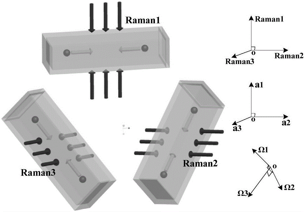
[0043] Such as figure 1 The schematic diagram of the three interference cavities of the atomic inertial measurement device is shown, and the three groups of atomic interference cavities are placed parallel to the horizontal plane to form an equilateral triangle. In each interference cavity, two groups of cold atoms are formed through two grou...


PUM


Abstract

The invention discloses a cold atom interferometry principle-based inertia measuring device. The cold atom interferometry principle-based inertia measuring device comprises three inertia measuring units, a Raman laser, and a light dividing device with adjustable splitting ratio; each inertia measuring unit comprises a single-mode narrow linewidth laser, an interferometic cavity, a optical fiber beam splitter, four acoustic optical modulators (AOM), and one electrooptical modulator (EOM); the interferometic cavities are filled with rubidium atomic vapor; Raman laser light send by the Raman laser can be divided into three beams of Raman laser light via the light dividing device with adjustable splitting ratio, and the three beams of Raman laser light are send to the three inertia measuring units; wherein the incidence directions of the three beams of Raman laser light are orthogonal to each other. According to the cold atom interferometry principle-based inertia measuring device, a reasonable structure scheme is adopted; three atom interferometers are arranged in a pyramid mode, so that sensitive acceleration directions of the atom interferometers are orthogonal to each other, and sensitive angular velocity directions are orthogonal to each other. One set of laser system is shared by the three atom interferometers, so that synchronization of atom interference process is realized, and the atom interferometer-based inertia measuring units are sensitive to inertial parameters with six degrees of freedom simultaneously.

Description

technical field [0001] The invention relates to the technical field of atomic inertial measurement, in particular to a high-precision inertial measurement device, which is suitable for platforms with high concealment and long readjustment periods of navigation systems. Background technique [0002] The positioning error of the inertial navigation system will diverge over time, resulting in an increasing positioning error. To manufacture a high-precision inertial navigation system, high-precision inertial devices must be required. So far, gyroscopes have experienced milestone development stages such as traditional liquid floating gyroscopes, electrostatic gyroscopes, ring laser gyroscopes, and fiber optic gyroscopes. With the rise of atomic optics and the development of laser technology, atomic gyroscopes and atomic accelerometers based on matter wave interference have become a hot research topic at home and abroad, and are considered to be the main direction for the develop...

Claims


Application Information

Patent Timeline
IPC IPC(8): G01C21/16
CPCG01C21/16
Inventor 钟山毛海岑黄海王四林宣扬陆家兵
Owner NO 717 INST CHINA MARINE HEAVY IND GRP
Learn More