
Manufacture method of embedded circuit board

A manufacturing method and circuit board technology, which is applied in the fields of printed circuit manufacturing, circuit lamination, printed circuit, etc., can solve the problems of alignment deviation, expansion and contraction value mismatch, and easy deviation, so as to reduce exposure offset and improve Alignment accuracy, effect of reducing wiring space

Active Publication Date: 2015-11-18
GCI SCI & TECH
View PDF7 Cites 7 Cited by
  • Summary
  • Abstract
  • Description
  • Claims
  • Application Information

AI Technical Summary

Problems solved by technology

However, the alignment accuracy between the sub-board and the mother board embedded in the existing embedded circuit board is low, which has become a bottleneck restricting the development of this type of circuit board.
[0003] The existing embedded circuit board manufacturing process is usually to make the sub-board, the embedded motherboard and the base motherboard circuit separately, open the accommodation groove in the embedded motherboard, and finally place the daughter board, the embedded motherboard and the base motherboard. The base motherboard is pressed together by prepreg flow glue at one time, and there is a risk of alignment deviation when the daughter board is placed in the embedded mother board's accommodating groove. This deviation will affect the alignment between the daughter board's graphics and the embedded motherboard's graphics. Accuracy, and in the process of pressing, the expansion and contraction value of the sub-board graphics and the embedded master graphics do not match, and it is easy to be misaligned, resulting in short scraps in the circuit board

Method used


Image

  • Manufacture method of embedded circuit board
  • Manufacture method of embedded circuit board
  • Manufacture method of embedded circuit board

Examples


Embodiment Construction

[0044] The following will clearly and completely describe the technical solutions in the embodiments of the present invention with reference to the accompanying drawings in the embodiments of the present invention. Obviously, the described embodiments are only some, not all, embodiments of the present invention. Based on the embodiments of the present invention, all other embodiments obtained by persons of ordinary skill in the art without creative efforts fall within the protection scope of the present invention. It should be noted that the serial numbers before each step in the embodiment are only for convenience of description, and there is no necessary sequence between each step, which should not be regarded as a limitation of the present invention.

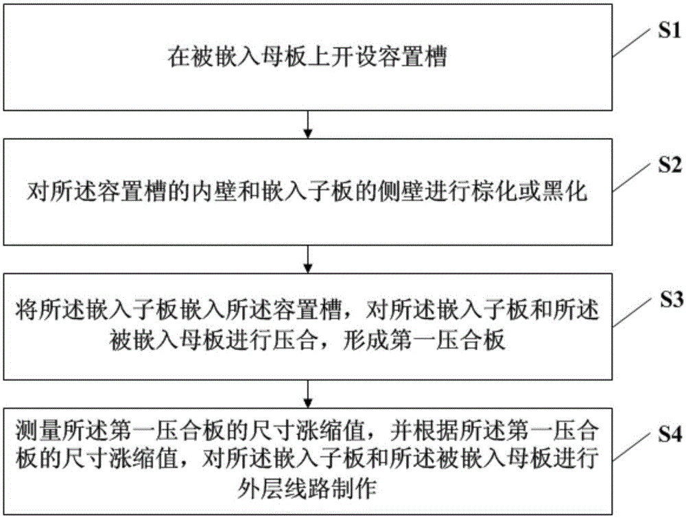
[0045] see figure 1 , is a schematic flowchart of an embodiment of the method for manufacturing an embedded circuit board provided by the present invention.

[0046] The method for manufacturing an embedded circuit board pro...


PUM


Abstract

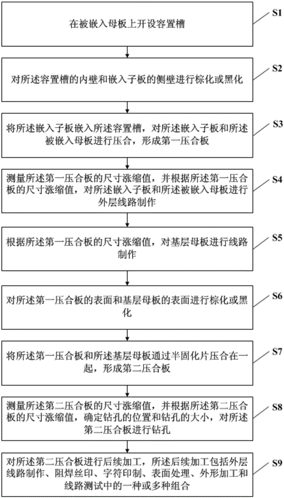
The invention discloses a manufacture method of an embedded circuit board. The method comprises that an accommodation groove is formed in a motherboard into which a board is embedded; the inner wall of the accommodation groove and the sidewall of an embedded daughter board is browned or blackened; the embedded draught board is embedded into the accommodation groove, the daughter board and the mother board are compressed to form a first compression board; and the size expansion and contraction value of the first compression board is measured, and external lines of the daughter board and the motherboard are prepared according to the size expansion and contraction value. According to the manufacture method, the external lines of the daughter board and the motherboard are prepared together, the problem of offset does not exist in the daughter board and the motherboard, and the aligning precision of patterns of the daughter board with patterns of the motherboard is greatly improved.

Description

technical field [0001] The invention relates to the technical field of printed circuit board (Printed Circuit Board, referred to as PCB) manufacturing technology, in particular to a method for manufacturing an embedded circuit board. Background technique [0002] With the development of the electronics industry, the size of electronic products is getting smaller and smaller, and the power density is getting higher and higher. How to find low-cost, local high-frequency circuit boards has become a huge challenge for the design of today's electronics industry. At present, there is a relatively new method in the circuit board manufacturing industry to solve the problem of high frequency and cost-embedded circuit board. However, the alignment accuracy between the sub-board and the motherboard embedded in the existing embedded circuit board is low, which has become a bottleneck restricting the development of this type of circuit board. [0003] The existing embedded circuit board...

Claims


Application Information

Patent Timeline
IPC IPC(8): H05K3/36
CPCH05K1/142H05K3/36H05K2203/06H05K2203/166
Inventor 谢新中李金鸿
Owner GCI SCI & TECH
Learn More