Dump truck

A technology of dump trucks and vehicles, which is applied to the arrangement of loading and unloading vehicles, motor vehicles, and vehicles used for freight transportation, etc. It can solve the problems of inability to calculate the rotation angle, more faults of sensing equipment, and increased maintenance costs.

Active Publication Date: 2015-11-18
NIHON KENKI CO LTD
View PDF7 Cites 2 Cited by
  • Summary
  • Abstract
  • Description
  • Claims
  • Application Information

AI Technical Summary

Problems solved by technology

[0010] In addition, with regard to the technology disclosed in JP-A-2010-190806, dump trucks operate in a harsher environment than normal mobile bodies, and as a result, there are more failures of sensor equipment, and the number of sensors such as position estimating devices increases. would be linked to increased opportunities for maintenance
That is, the increase in sensors results in an increase in not only the introduction cost but also the maintenance cost. Therefore, when considering the use in dump trucks, a method is desired that can always accurately measure the sensor without increasing the number of sensors. Presumed pose
However, if the attitude of the dump truck is estimated simply by using only two position estimating devices, the rotation angle around the line segment connecting the two position estimating devices cannot be calculated, and thus the posture cannot be uniquely determined.

Method used


Image

  • Dump truck
  • Dump truck
  • Dump truck

Examples


no. 1 Embodiment approach >

[0038] In the first embodiment, the attitude of the dump truck is obtained while referring to the road gradient information stored in the storage device (topological map database) 106 together with the map data showing the travel route of the dump truck. In addition, for the sake of convenience, although the road surface on which the dump truck travels has a vertical slope in this embodiment, it does not have a cross slope (the slope angle is zero).

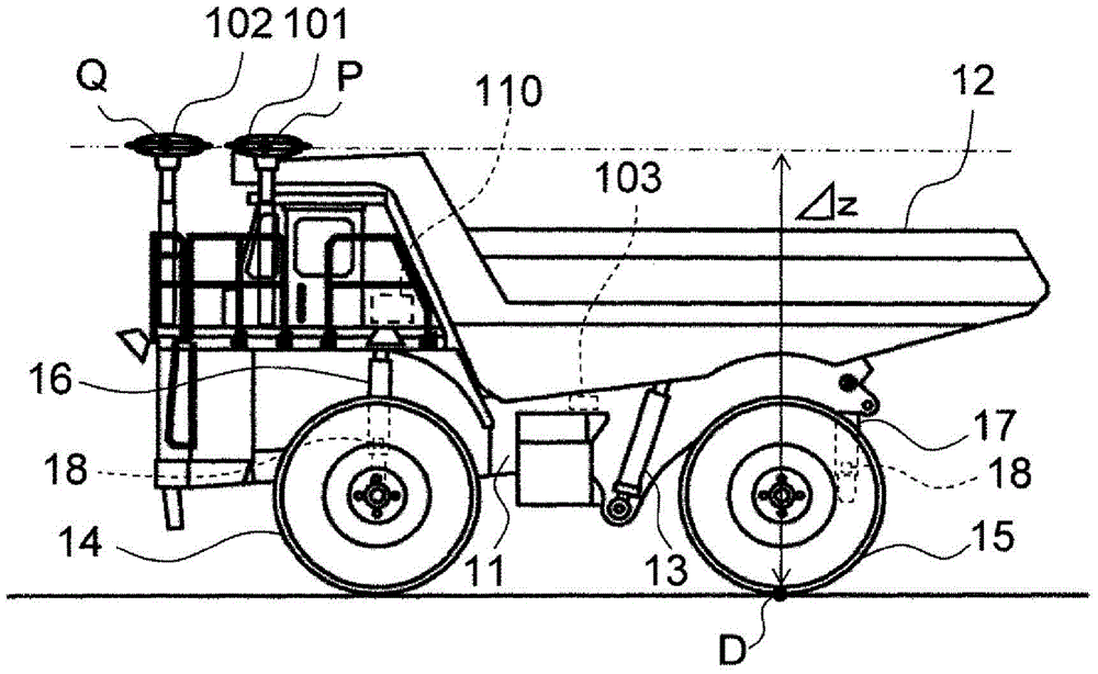
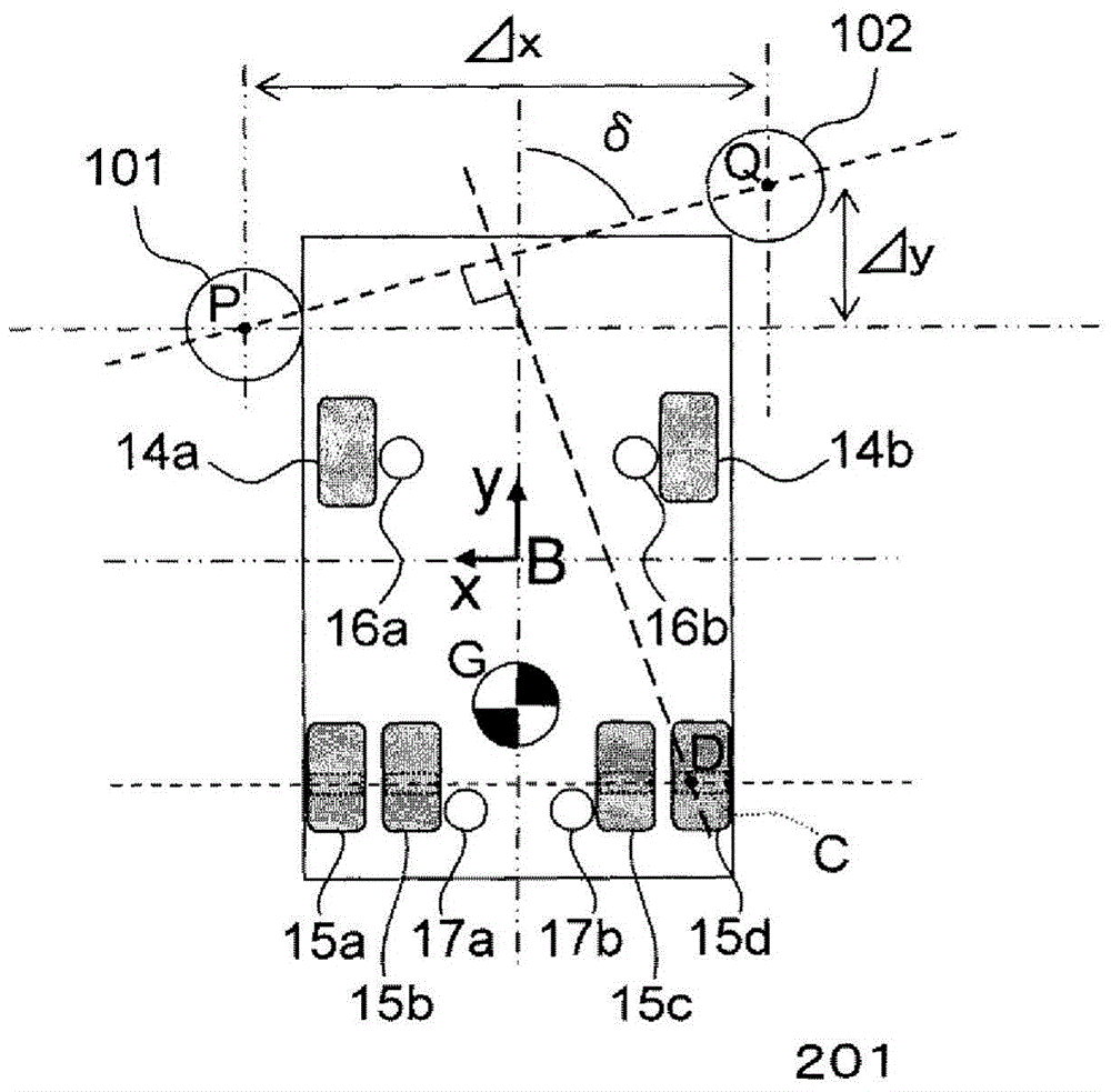
[0039] figure 1 A schematic configuration of a dump truck according to a first embodiment of the present invention is shown. The dump truck shown in this figure has: a vehicle frame 11; a cargo box (body) 12 mounted on the vehicle frame to undulate freely; Root hydraulic cylinders 13, 13; 2 front wheels 14a, 14b rotatably installed in front of the vehicle frame 11; 4 rear wheels 15a, 15b, 15c, 15d rotatably installed in the rear of the vehicle frame; front shock absorbers 16a, 16b for suspending the vehicle frame 11 on the fron...

no. 2 Embodiment approach >

[0088] The second embodiment of the present invention is characterized in that time-series information on the positions of points P and Q obtained via the GPS receivers 101 and 102 is stored in the storage device 106, a motion vector of the position data is calculated based on the time-series information, and The gradient α of the road on which the dump truck travels is calculated based on the movement vector. This embodiment differs from the first embodiment in the data structure of the storage device 106 and the calculation of the gradient α by the computer 110. However, other configurations including posture calculation processing are the same as those of the first embodiment, and thus description thereof will be omitted. .

[0089] Figure 8 It is a diagram showing the part related to the time-series information of the positions of points P and Q in the data structure of the storage device 106 according to the second embodiment of the present invention. As shown in the f...


PUM


Abstract

A dump truck comprising a plurality of rear wheels (15) rotatably attached to a frame (11) and two GPS receivers (101, 102) arranged so as to be mutually staggered in the vehicle front/rear direction. In a vehicle coordinate system (B) set for the dump truck, any point selected from a section (C) in which the plurality of rear wheels are in contact with the ground is used as a reference point (D). The two GPS receivers are arranged such that a vertical line can be drawn to the reference point (D) from a line segment (PQ) joining two points (P, Q) having the positions thereof calculated by the two GPS receivers. As a result, two position estimation means can be used and posture can always be accurately estimated without stopping the operation of mining equipment.

Description

technical field [0001] The present invention relates to dump trucks that move in mines or construction sites. Background technique [0002] The posture of a dump truck used in a mine or a construction site is represented by a roll angle (roll angle), a pitch angle (pitch angle), and a yaw angle (yaw angle). When the surface perpendicular to the direction of gravity is defined as a horizontal plane, the front and rear axes of the dump truck rotate around the left and right axes (lateral axes) orthogonal to the front and rear axes, and the angle formed with the horizontal plane is the pitch angle. The left-right axis rotates around the front-rear axis and forms an angle with the horizontal plane as a roll angle. Furthermore, the yaw angle which is the rotation angle of the vertical axis which is perpendicular to both the front-rear axis and the left-right axis of the dump truck is the azimuth angle. [0003] In connection with dump trucks, Japanese Patent Application Laid-Op...

Claims


Application Information

Patent Timeline
Patent Type & Authority Applications(China)
IPC IPC(8): G01C15/00B60P1/04
CPCB60P1/04B60P1/045G01C15/00G01S5/017G01S19/53G01C5/00G01C9/02
Inventor 板东干雄佐藤隆之石本英史
Owner NIHON KENKI CO LTD
Why Eureka
Try Eureka