Fuel cell system

A fuel cell system and fuel cell technology, used in fuel cells, fuel cell additives, fuel cell grouping, etc., can solve problems such as low effective power generation balance, and achieve the effects of high service life and reduced conductivity

Inactive Publication Date: 2015-11-18
BAYERISCHE MOTOREN WERKE AG
View PDF7 Cites 1 Cited by
  • Summary
  • Abstract
  • Description
  • Claims
  • Application Information

AI Technical Summary

Problems solved by technology

However, due to the series connection of the individual fuel cells, the very low effective power produced by the slow heating of the (relatively few) individual fuel cells in the end regions of the stack has a negative effect on the energy balance of the entire fuel cell stack. influences

Method used


Image

  • Fuel cell system
  • Fuel cell system
  • Fuel cell system

Examples


Embodiment Construction

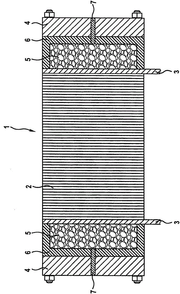
[0022] according to figure 1 , the fuel cell system of the present invention includes a plurality of individual fuel cells 2 combined into a fuel cell stack 1 or stack 1 (and stacked up and down here), wherein the stack of individual fuel cells 2 is at each end The upper part is delimited by a collecting electrode 3, on the side of the collecting electrode facing away from the individual fuel cells, an end plate 4 is arranged. An insulating plate 6 is now also arranged between the respective collector 3 and the respective end plate 4 .

[0023] In addition, a heat accumulator 5 , which is now arranged in a recess in the insulating plate 6 , rests on the side facing away from the individual fuel cells 2 on the collecting electrode 3 . The heat accumulator 5 is designed as a latent heat accumulator (with phase change material PCM) or can be formed as a sorption accumulator (for example with zeolites). As an option (but not shown), the heat accumulator 5 can also be arranged in...


PUM


Abstract

The invention relates to a fuel cell system, comprising a plurality of individual fuel cells (2) which are combined to form a fuel cell stack, and two current collectors (3) which adjoin the two individual fuel cells at the ends, an end plate (4) adjoining the current collectors in each case directly or with the interposition of an insulation plate (6), wherein a heat accumulator (5) is provided in an adjacent manner on at least one of the current collectors (3) on the side facing away from the individual fuel cells (2). Said heat accumulator can be arranged in a recess of the end plate (4) or of the optionally present insulation plate (6), and a compensation reservoir for a change in volume of the heat accumulator (5) may be provided.

Description

technical field [0001] The present invention relates to a fuel cell system, which includes a plurality of individual fuel cells combined into a fuel cell stack and two collectors connected to the individual fuel cells at both end sides, on which the collectors are respectively directly There is an end plate connected to the ground or in the case of an insulating plate lined in the middle. Background technique [0002] Single fuel cells are usually connected in series to form a fuel cell stack (also referred to as a stack (Stack) herein) in order to achieve a higher voltage. On each end of a fuel cell stack there is an end plate which exerts a uniform surface pressure on the individual fuel cells or clamps the individual fuel cells into a fuel cell stack and thus guarantees Reliable separation of the different fluid flows guided within the fuel cell stack from one another and tightness from the outside world. Between the end plate and the stack of individual fuel cells ther...

Claims


Application Information

Patent Timeline
Patent Type & Authority Applications(China)
IPC IPC(8): H01M8/04H01M8/24H01M8/10
CPCH01M8/2475H01M8/0267H01M8/04052H01M8/04268H01M2008/1095H01M2250/20Y02E60/521Y02T90/32B60L50/72B60L58/32H01M8/241Y02E60/50Y02T90/40
Inventor S·哈斯R·希默
Owner BAYERISCHE MOTOREN WERKE AG
Why Eureka
Try Eureka