Pulse cycle detection equipment and method and wearable electronic equipment

A technology of periodic detection and pulse, applied in diagnostic recording/measurement, medical science, sensors, etc., can solve problems such as false detection or missed detection, poor anti-interference ability and measurement accuracy, and large amount of calculation

Active Publication Date: 2015-11-25
BOE TECH GRP CO LTD
View PDF7 Cites 23 Cited by
  • Summary
  • Abstract
  • Description
  • Claims
  • Application Information

AI Technical Summary

Problems solved by technology

Therefore, the traditional differential threshold method has a large amount of calculation and is difficult to meet the requirements of real-time applications.
In addition, because the pulse wave detection site is usually located in the peripheral blood circulation, the blood vessels have a strong smoothing effect on the pulse wave, especially when the subject's pulsation is weak, so the amplitude of the pulse wave and the steepness of the rising edge are obvious Reduced, making the anti-interference ability and measurement accuracy of the traditional differential threshold method very poor, resulting in frequent false detection or missed detection

Method used


Image

  • Pulse cycle detection equipment and method and wearable electronic equipment
  • Pulse cycle detection equipment and method and wearable electronic equipment
  • Pulse cycle detection equipment and method and wearable electronic equipment

Examples


Embodiment Construction

[0026] Various embodiments of the present invention will be described in detail below in conjunction with the accompanying drawings.

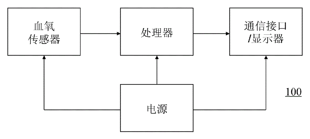
[0027] figure 1 A block diagram of a pulse cycle detection device 100 according to an embodiment of the present invention is schematically illustrated. The pulse cycle detection device 100 may include a sensor, a processor, a power supply, and a communication interface and / or a display. As shown, the sensor, processor, and communication interface and / or display are in turn electrically connected, and a power source is electrically connected to each component. The sensor is used for sensing the pulse wave signal of the subject. In particular, the sensor may be a transmissive blood oxygen sensor or a reflective blood oxygen sensor. The processor can be used to process the analog-to-digital converted digital pulse wave signal sensed by the blood oxygen sensor to detect the pulse cycle of the subject. The processor can also be used to calculate...


PUM


Abstract

The invention discloses pulse cycle detection equipment, which comprises a sensor for sensing and detecting a pulse wave signal of a detected subject; and a processor for processing the digital pulse wave signal which is sensed and detected by the sensor and undergoes analog-digital conversion so as to detect the pulse cycle of the detected subject, wherein the processor is configured to implement the following operations: as time goes on, calculating a differential value of the digital pulse wave signal; determining that the pulse wave signal reaches at the maximum value point and recording a time value corresponding to the maximum value point as the differential value is converted from a positive number to a negative number; recognizing the latest recorded maximum value point in the past time as the peak point of the pulse wave signal when the differential value is less than a dynamic threshold; and calculating a difference between the time values corresponding to the two continuous peak points so as to export the pulse cycle. The invention also discloses a pulse cycle detection method and wearable electronic equipment. By virtue of the pulse cycle detection equipment and the method, the real-time performance and the precision of pulse cycle detection can be improved.

Description

technical field [0001] The invention relates to the technical field of vital sign detection, in particular to a pulse cycle detection device and method and a wearable electronic device. Background technique [0002] In recent years, wearable health monitoring devices have received increasing attention. Among wearable pulse (heart rate) monitoring devices, blood oxygen sensor-based devices are one of the common types. The principle of pulse measurement is based on the following fact: the absorption of light by oxygenated hemoglobin and reduced hemoglobin in blood changes with the periodic change of pulse wave, and pulse detection can be realized by detecting the change of light absorption by blood. In other words, the pulse wave signal is modulated in the measured light signal. The pulse wave period or heart rate can be calculated by analyzing the photoplethysmography signal (PPG) detected by the blood oxygen sensor (pulse frequency can be considered as heart rate). [000...

Claims


Application Information

Patent Timeline
Patent Type & Authority Applications(China)
IPC IPC(8): A61B5/0245
CPCA61B5/02108A61B5/02416A61B5/02427A61B5/02438A61B5/14552A61B5/7239
Inventor 袁佐
Owner BOE TECH GRP CO LTD
Why Eureka
Try Eureka