Endoscopic cutting stapler

A stapler and laparoscopic technology, applied in the field of medical devices, can solve the problems of cumbersome operation, loss of surgical field, increase of potential damage, etc., and achieve the effect of improving surgical effect, reducing surgical damage, and reducing diameter

Inactive Publication Date: 2015-11-25
李学军
View PDF5 Cites 6 Cited by
  • Summary
  • Abstract
  • Description
  • Claims
  • Application Information

AI Technical Summary

Problems solved by technology

Therefore, the existing laparoscopic cutting stapler cannot be directly inserted from the observation hole or the operation hole of the puncture device. The current method is to take out one of the puncture devices and re-puncture a puncture device with a diameter of 15 mm operation hole. The operation can only be continued by passing the anastomotic function part of the laparoscopic cutting stapler through the oper

Method used


Image

  • Endoscopic cutting stapler
  • Endoscopic cutting stapler
  • Endoscopic cutting stapler

Examples


Embodiment 1

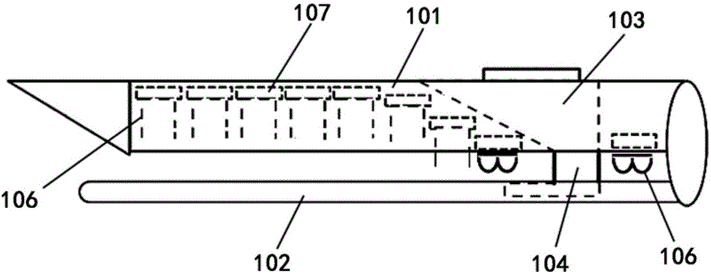
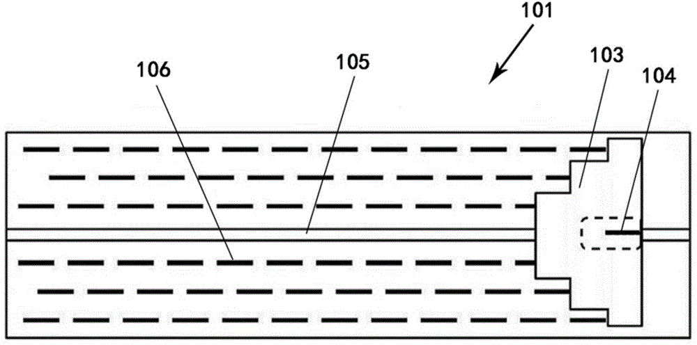
[0062] Such as Figure 5 As shown, the endoscopic cutting stapler of this embodiment includes an anastomosis function part, a connecting rod and an excitation handle, and the anastomosis function part includes a staple cartridge 1, an abutment seat 2, an "I" beam member 3 and a blade ( The blade is not shown in the figure), the staple cartridge 1 is set correspondingly to the nail abutment seat 2, and a part of the "I" beam member 3 is located in the staple cartridge 1, and a part is located in the nail abutment seat 2; the blade and the "work" The word beam member 3 is connected and located between the nail cartridge 1 and the nail abutment seat 2 . Among them, in order to clearly show

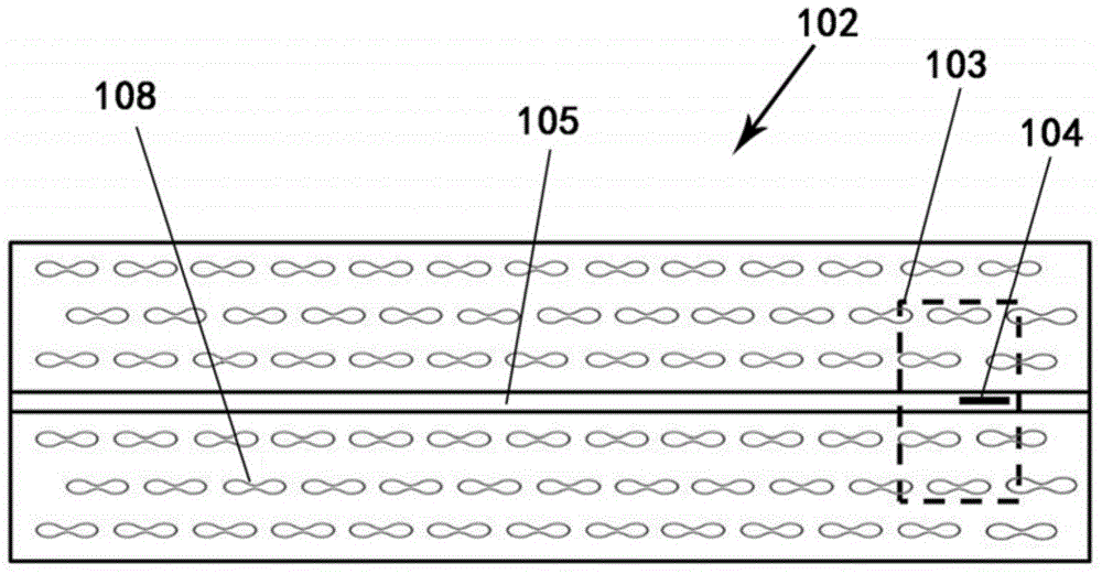
[0063] The side of the staple cartridge 1 opposite to the nail anvil 2 is the first contact surface 5, the side of the nail anvil 2 opposite to the staple cartridge 1 is the second contact surface 6, and the first contact surface 5 is formed by being concave toward the interior of the staple...

Embodiment 2

[0069] The difference between this embodiment and the first embodiment lies in that the bending directions of the arc-shaped curved surfaces of the first contact surface 5 and the second contact surface 6 are different. Such as Figure 6 As shown, the first contact surface 5 is a convex arc surface formed outwardly toward the nail anvil 2, and the second contact surface 6 is a concave arc surface formed to be concave toward the interior of the nail anvil 2 and matched with the convex arc surface; The surface 12 is the same convex arc surface as the first contact surface 5; the staples 9 are arranged in a convex arc shape corresponding to the first contact surface 5, so that the "I" beam member 3 can sequentially push the staples 9 for stitching organize. . When the activation handle is activated once, when the "I" beam member 3 moves forward, the pushing surface 12 can accurately push the abutting block 11, thereby pushing out the staples to suture the tissue. The second em...

Embodiment 3

[0071] The first contact surface 5 and the second contact surface 6 may also be polyhedral in addition to being arc-shaped. Such as Figure 7 As shown, the first contact surface 5 is a concave polyhedral shape formed by being concave toward the interior of the staple cartridge 1, the second contact surface 6 is a convex polyhedral shape formed by protruding outward toward the nail cartridge 1 and matching the concave polyhedral shape, and the pushing surface 12 It is the same concave polyhedron shape as the first contact surface 5 .

[0072] continue to combine Figure 7 , in this embodiment, the concave polyhedron shape of the first contact surface 5 includes a first plane 14 , two second planes 15 and two third planes 16 . The first plane 14 is located at the center of the first contact surface 5 ; both sides of the first plane 14 are respectively connected to the second plane 15 and the third plane 16 in sequence. The connection of two adjacent planes forms a knuckle, th...


PUM


Abstract

The invention discloses an endoscopic cutting stapler, comprising a stapling functional member, a connecting rod and a trigger handle. The stapling functional member comprises a staple magazine, a staple holder, an I-shaped beam member and a blade; one face, facing the staple holder, of the staple magazine is a curved face which enables staples to close and staple tissues when the staple magazine and the staple holder are closed; a plurality of rows of staples are arranged in the staple magazine, and the staples in accordance with the curved face of a first contact face are arranged in a curvilinear form; a push face, used for contacting holding blocks and pushing the same, of the I-shaped beam member is a curved face the same as the first contact face in shape. The contact faces of the staple holder and the staple magazine are modified into arc faces or bent faces (curved faces), overall diameter of the stapling functional member can be reduced at the premise of not reducing the width of tissues contained by the contact faces and ensuring closing effect of stapling, and thus, operations are made coherent and direct, surgical injury is reduced and operation results are improved.

Description

technical field [0001] The invention relates to a stapler, in particular to a laparoscopic cutting stapler, which belongs to the field of medical instruments. Background technique [0002] In the surgical operation of medical science, minimally invasive surgery is becoming more and more widely used for its small trauma, fast healing and good effect, so the stapler that can be used under the endoscope is essential. [0003] Endoscopic cutting staplers are usually composed of stapling functional parts, connecting rods, activation handles and other components. During the operation, make several small wounds on the abdominal wall or chest wall, insert the puncture device, insert the anastomotic functional parts from the puncture device, and operate the activation handle from the outside of the body after reaching the selected position, so as to achieve rapid and effective cutting and suturing of tissues role. [0004] Such as Figure 1 to Figure 3 As shown, the anastomotic fun...

Claims


Application Information

Patent Timeline
IPC IPC(8): A61B17/072
CPCA61B2017/07271
Inventor 李学军
Owner 李学军
Why Eureka
Try Eureka