
A low heat source magnetic stirring device

A magnetic stirring device and heat source technology, applied in the directions of dissolution, mixer, chemical instrument and method, can solve the problems of high dependence on cooling medium, accelerated bearing wear, demagnetization bearing life, etc., to improve stirring transmission efficiency, eliminate diameter Effects of frictional force and high-efficiency torque transmission

Inactive Publication Date: 2017-02-15
白万本
View PDF7 Cites 0 Cited by
  • Summary
  • Abstract
  • Description
  • Claims
  • Application Information

AI Technical Summary

Problems solved by technology

[0003] Due to the axial thrust of the blades of the low-speed, super-high-torque side-entry magnetic stirring device and the large radial friction caused by the weight of the large rotor components, a large amount of mechanical friction heat is generated during the operation of the stirring equipment, which accelerates Due to the wear of the bearing, the coupling force of the magnetic drive is also weakened or even demagnetized due to temperature rise
At the same time, part of the mechanical kinetic energy is lost or the transmission efficiency is reduced.
[0004] In order to solve the problem of the influence of temperature on the weakening of the magnetic force, even demagnetization and bearing life, an internal pressure difference medium self-cooling circulation system or an external cooling circulation system is set up in the prior art, but for the presence of particles, suspended matter, etc. in the stirring system The use of internal pressure difference medium circulation cooling system obviously cannot meet the requirements of working conditions.
Similarly, the use of an external circulation system will inevitably require a continuous and uninterrupted supply of cooling medium (pure material), that is, a high degree of dependence on the cooling medium. If the cooling system has low or no pressure, there will be serious safety hazards in the operation of the equipment , for example: Chinese patent ZL201120189150.3 is a patent for a flue gas desulfurization stirring device, which adopts the method of cooling and flushing system to control the temperature rise, and also has a high degree of dependence on the cooling medium
[0005] Even if cooling is used in the prior art to control the temperature rise caused by frictional heat, it is essentially a process of waste of cooling medium resources and loss of mechanical kinetic energy

Method used


Image

  • A low heat source magnetic stirring device
  • A low heat source magnetic stirring device
  • A low heat source magnetic stirring device

Examples


Embodiment Construction

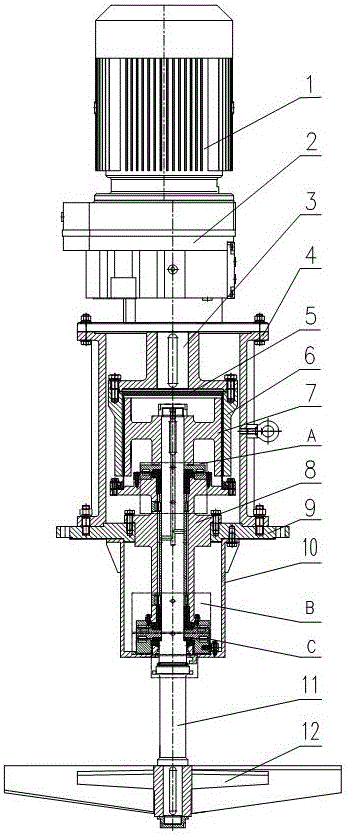
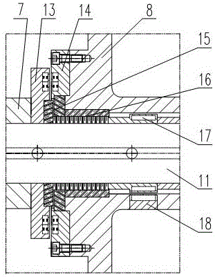
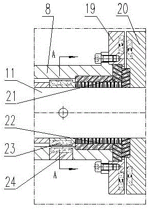
[0032] Such as figure 1 As shown, a low heat source magnetic stirring device comprises a support 4, a bearing housing 8 and a sealed barrel 10 arranged on the tower body flange 9, a reduction gear 2 connected to the active power motor 1 placed on the support 4, and a The magnetic transmission device in the bracket 4. The output shaft 3 of the reduction gear 2 is connected with the input shaft 11 through the magnetic transmission device, and the end of the input shaft 11 passing through the bearing housing 8 and the sealed barrel 10 is connected with the stirring paddle 12 .

[0033]The magnetic transmission device includes a driving magnetic rotor 6 and a driven magnetic rotor 7 placed in the bracket 4 . The active magnetic rotor 6 is connected with the output shaft 3 and coupled with the driven magnetic rotor 7; a spacer 5 is provided between the active magnetic rotor 6 and the driven magnetic rotor 7, and the spacer 5 is fixed on the flange of the bearing housing 8; The dr...


PUM


Abstract

The invention relates to a low heat source magnetic stirring device, which comprises a support, a bearing box, a sealing bucket, a speed reducer and a magnetic transmission device, wherein the speed reducer is connected with a source power motor, an output shaft of the speed reducer is connected with an input shaft, the input shaft is connected with a stirring blade, the magnetic transmission device comprises a drive magnetic rotor and a driven magnetic rotor which are arranged in the support, the drive magnetic rotor is connected with the output shaft, and is coupled with the driven magnetic rotor, an isolation sleeve is arranged between the drive magnetic rotor and the driven magnetic rotor, the driven magnetic rotor is connected with the input shaft, magnetic suction components and magnetic spending components are respectively arranged between the input shaft and the rear end of the bearing box and between the input shaft and the front end of the bearing box, two groups of magnetic slip sleeve components are respectively arranged in the input shaft and an inner cavity of a base body of the bearing box, a magnetic locking component is arranged between the input shaft and the sealing bucket, and a cooling device is respectively connected outside a cavity formed between an inner cavity of the isolation cover, the input shaft and the bearing box and an inner cavity of the sealing bucket. The low heat source magnetic stirring device can effectively improve stirring drive efficiency.

Description

technical field [0001] The invention relates to a magnetic stirring device, in particular to a low heat source magnetic stirring device. Background technique [0002] With the rapid development of magnetic application science, magnetic transmission is the development trend of replacing traditional mechanical seals, with the characteristics of no leakage, no pollution, and environmental protection. High-speed, low-torque magnetic transmission equipment has formed a situation of large-scale production and industrial application. In recent years, low-speed, super-high-torque side-entry magnetic stirring devices are a new type of industry based on mature magnetic transmission technology. [0003] Due to the axial thrust of the blades of the low-speed, super-high-torque side-entry magnetic stirring device and the large radial friction caused by the weight of the large rotor components, a large amount of mechanical friction heat is generated during the operation of the stirring eq...

Claims


Application Information

Patent Timeline
Patent Type & Authority Patents(China)
IPC IPC(8): B01F13/08
Inventor 白万本王兴明周龙德
Owner 白万本
Learn More