New Structure of Guide Pillar and Guide Bush for Crankshaft Forging Die

A guide sleeve and guide post technology, applied in the field of forging, can solve the problems of unstable forging process, small operation space, complicated crankshaft forgings, etc., achieve large use value and economic value, convenient and fast operation and use, and solve the control of misalignment difficult effect

Inactive Publication Date: 2018-03-27
重庆大江杰信锻造有限公司
View PDF6 Cites 1 Cited by
  • Summary
  • Abstract
  • Description
  • Claims
  • Application Information

AI Technical Summary

Problems solved by technology

[0003] In actual production, due to the complexity of crankshaft forgings, the rigidity and orientation of production equipment are difficult to guarantee absolutely, and the mold loading and other reasons lead to a certain degree of misalignment in the final forgings, which affects the quality of forgings
In general forging dies, only equipment guide posts, guide sleeves or die locks are used as guides. There is a large misalignment of forgings, and the forging process is unstable. Therefore, the following technical difficulties and quality problems are likely to occur during crankshaft forging:
[0004] 1. The displacement of forgings is large, and the shape, size and accuracy of forgings are difficult to guarantee;
[0005] 2. The operating space of forging workers, manipulators or walking beams is small, and it is inconvenient to transfer forgings between stations;
[0006] 3. The stability of the forging process is poor, and the shape and size of the forgings fluctuate greatly;
[0007] 4. It is inconvenient to operate and position the mold, the time for mold loading and mold debugging is long, and the scrap rate is high

Method used


Image

  • New Structure of Guide Pillar and Guide Bush for Crankshaft Forging Die
  • New Structure of Guide Pillar and Guide Bush for Crankshaft Forging Die
  • New Structure of Guide Pillar and Guide Bush for Crankshaft Forging Die

Examples


Embodiment Construction

[0021] The present invention will be described in further detail below in conjunction with specific embodiments and accompanying drawings.

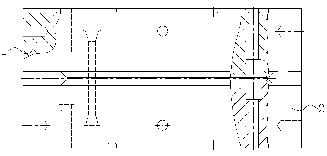
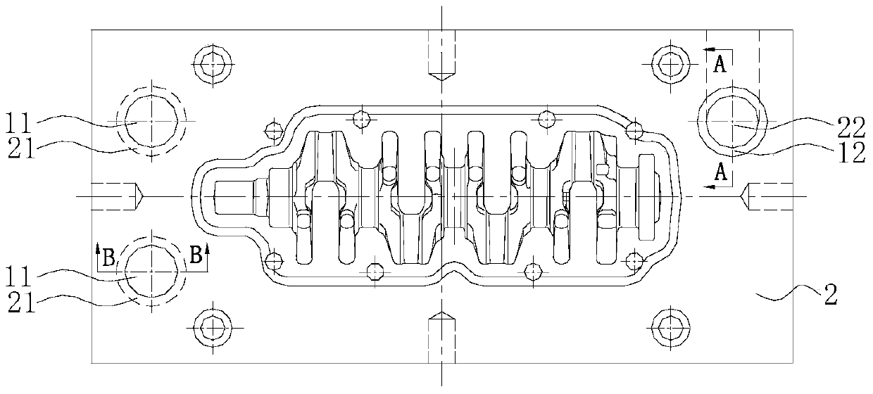
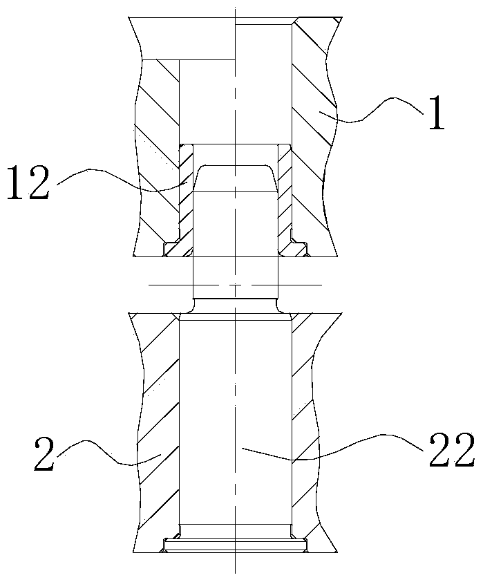
[0022] a kind of like Figure 1-Figure 5 The new guide post and guide sleeve structure of the crankshaft forging die is used to guide the relative movement between the upper die 1 and the lower die 2 of the forging die, which includes the upper die 1, the lower die 2 and the upper die 1. Three guide posts and guide sets on the parting surface between the lower dies 2, any set of guide posts and guide sets includes guide sleeves that are only fixedly positioned on the die forging upper die 1 or die forging lower die 2, and Only fixedly positioned on the lower die forging die 2 or upper die forging die 1 and corresponding to the guide sleeve on the upper die forging die 1 or lower die forging die 2 and can slide through and be positioned in the guide sleeve guide posts, wherein the three guide posts and guide sets include two guide posts a...


PUM


Abstract

The invention discloses a novel guide post and guide sleeve structure of a crankshaft forging die, which is used for guiding the relative movement between the upper and lower dies of the forging die. Three guide posts and guide sets on the parting surface, any set of guide posts and guide sets includes a guide sleeve that is only fixedly positioned on the upper or lower die forging, and a guide sleeve that is only fixed on the lower or upper die forging and Corresponding to the guide sleeve on the die forging upper or lower die and can slide through the guide post positioned in the guide sleeve, wherein the three guide post guide sleeve set includes two guide post guide sleeves at both ends of one side of the parting surface A set of guide posts and guide sleeves on the other side of the parting surface that is only positioned at one end, and two sets of guide posts and guide sleeves, and one set of guide posts and guide sleeves are respectively placed on the guide posts and guide sleeves on the upper and lower dies for die forging. The distribution is set in reverse. The invention has a simple structure, is convenient for mold loading, mold changing, and debugging, and is convenient and quick to operate, effectively solves the problem of difficult control of forging misalignment, has high stability of forging process, and good product consistency.

Description

technical field [0001] The invention belongs to the technical field of forging, and in particular relates to a novel guide post and guide sleeve structure of a crankshaft forging die. Background technique [0002] The crankshaft is a key part of the engine, most of which are formed by forging. The typical process is: blanking-induction heating-blank making, pre-forging, final forging-trimming-correction-heat treatment-shot blasting-flaw detection-surface treatment -wrap up and store. Among them, the final forging process is an important process of forging forming, and the shape and precision of the crankshaft largely depend on the effect of final forging. [0003] In actual production, due to the complexity of the crankshaft forging, the rigidity and orientation of the production equipment are difficult to be absolutely guaranteed, and the mold loading and other reasons lead to a certain degree of misalignment in the final forging, which affects the quality of the forging. ...

Claims


Application Information

Patent Timeline
Patent Type & Authority Patents(China)
IPC IPC(8): B21J13/02B21D37/12
Inventor 胡永毅董旭刚潘成海陈必祥何海兵
Owner 重庆大江杰信锻造有限公司
Why Eureka
Try Eureka