Tooling for fastening metal reinforcement on the leading edge of a turbine engine blade, and a method using such tooling

US20160076387A1Active Publication Date: 2016-03-17SAFRAN +1

Image

  • Tooling for fastening metal reinforcement on the leading edge of a turbine engine blade, and a method using such tooling
  • Tooling for fastening metal reinforcement on the leading edge of a turbine engine blade, and a method using such tooling
  • Tooling for fastening metal reinforcement on the leading edge of a turbine engine blade, and a method using such tooling

Examples


Embodiment Construction

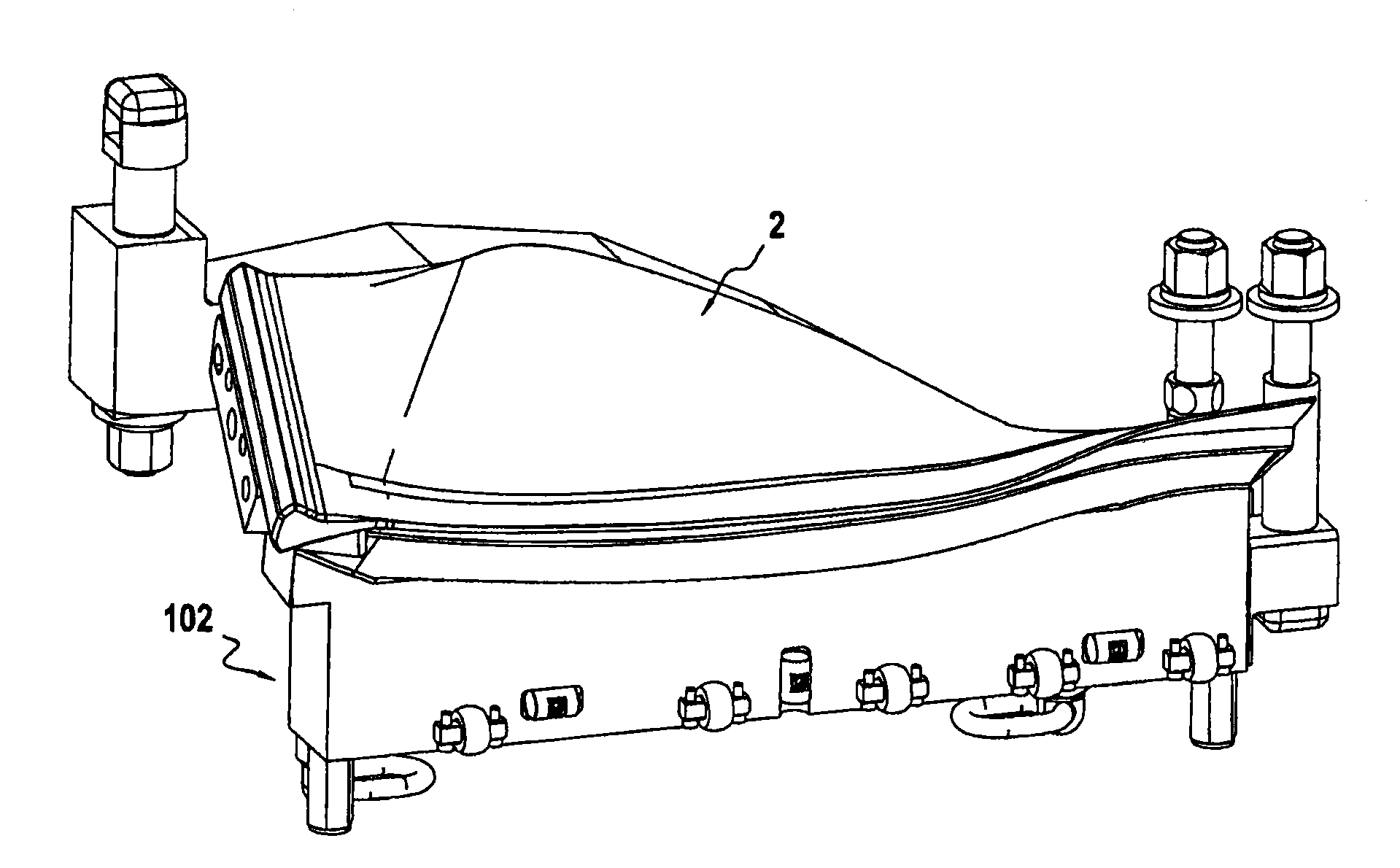
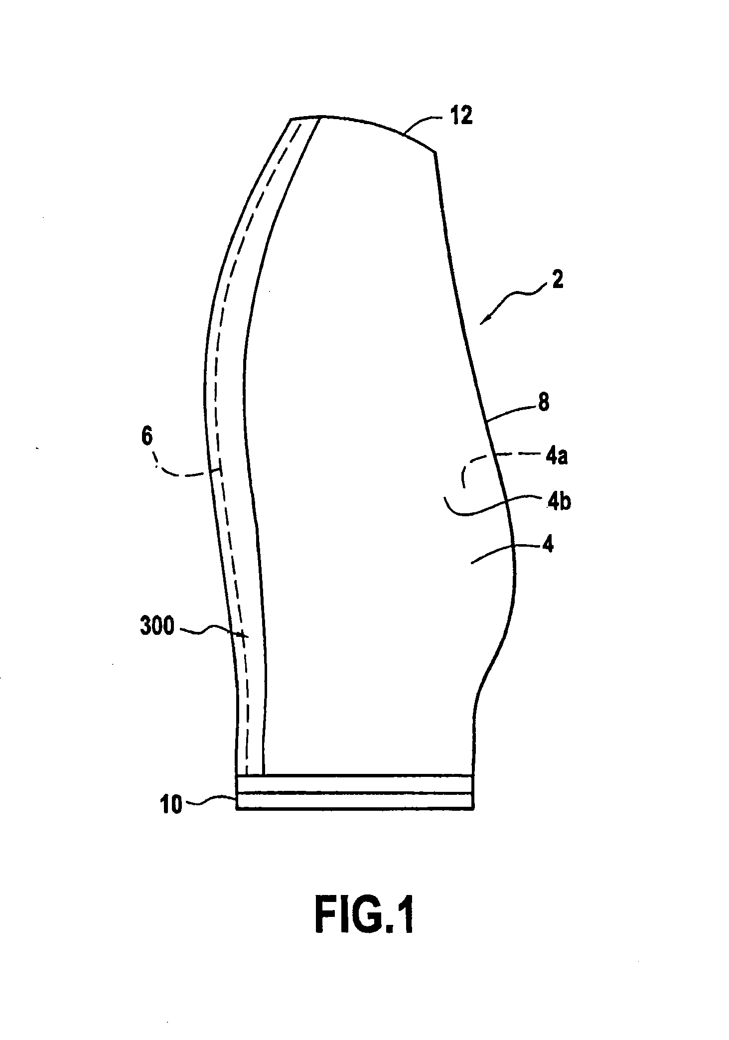
[0027]The invention applies to fastening metal reinforcement on the leading edge of any turbine engine blade. A preferred application of the invention lies in fastening reinforcement made of titanium on the leading edge of a turbojet fan blade made of carbon fiber composite material, such as that shown in FIG. 1.

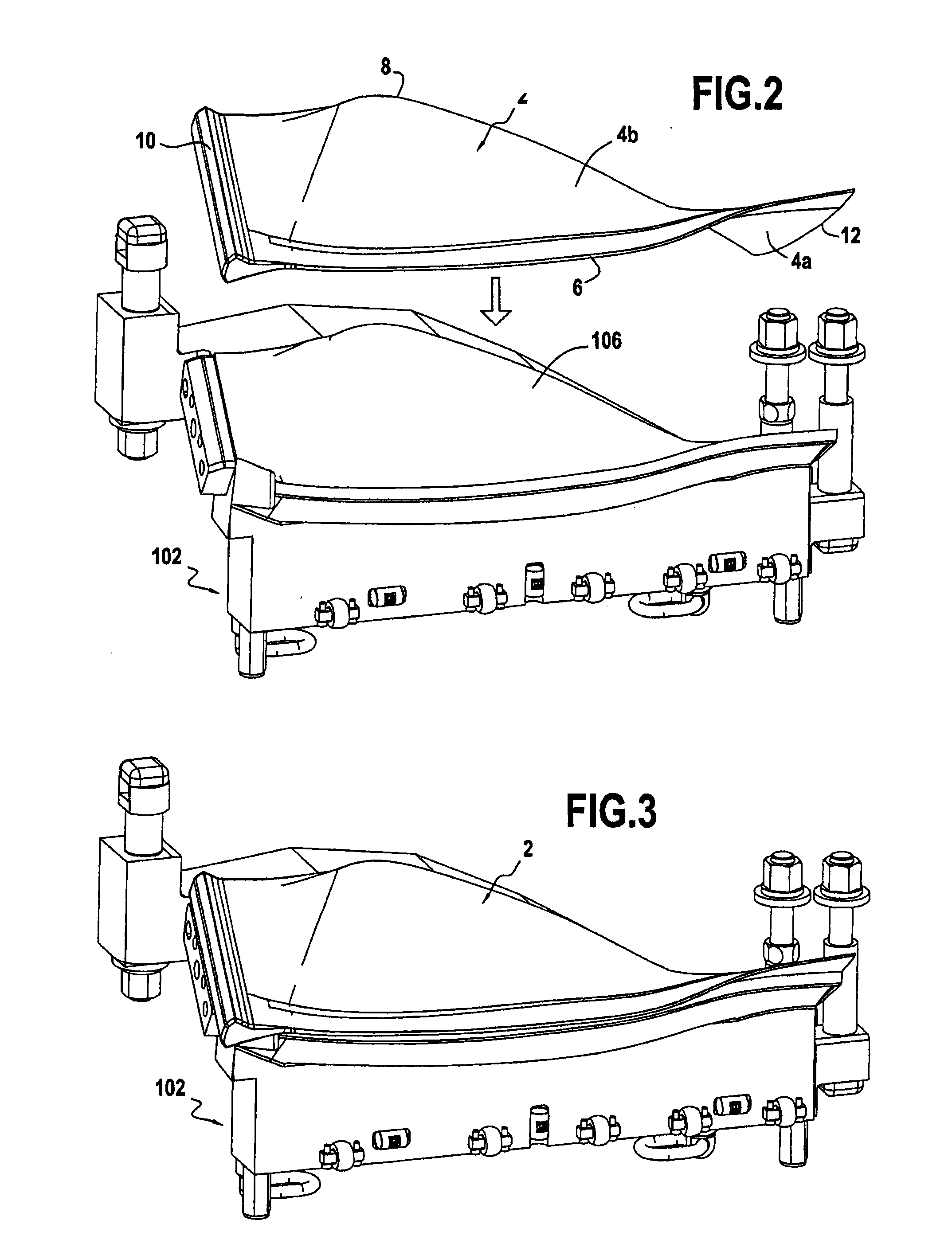
[0028]In known manner, a turbojet fan blade 2 made of composite material comprises an airfoil 4 having a suction side surface 4a and a pressure side surface 4b. The pressure- and suction-side surfaces extend between a leading edge 6 and a trailing edge 8. The blade also has a root 10 for mounting on a rotor disk.

[0029]The composite material blade 2 is obtained by draping or weaving a composite material. By way of example, the composite material may be an assembly of carbon fibers that are woven and molded by an injection method known as resin transfer molding (RTM).

[0030]The blade 2 also has metal structural reinforcement 300 that is adhesively bonded on the leading edge 6, ...


PUM

PropertyMeasurementUnit
Pressureaaaaaaaaaa

Abstract

A tooling for fastening metal reinforcement on the leading edge of a turbine engine blade, the tooling including a blade support for receiving a blade while leaving surfaces of the leading edge of the blade disengaged; and a leading edge reinforcement support on which the blade support is designed to be mounted, and including two lateral wedges between which the metal reinforcement for the leading edge of the blade is positioned, the wedges being suitable for being capable of moving towards each other and apart from each other and each of them being provided with a suction grid for gripping the metal reinforcement, the leading edge reinforcement support further including heater elements for polymerizing an adhesive film applied on the leading edge surfaces of the blade.

Description

BACKGROUND OF THE INVENTION[0001]The present invention relates to the general field of turbine engines blades provided with metal reinforcement on their leading edges. The invention relates more particularly to tooling and to a method for fastening metal reinforcement on the leading edge of a turbine engine blade that is made of composite material.[0002]It is known for fan blades of a turbine engine that are made of composite material to be fitted with structural reinforcement made of metal that extends over the full height of each blade. Such reinforcement serves to protect a composite blade in the event of an impact against the fan of a foreign body, such as a bird being ingested by the turbine engine, for example.[0003]A known method of fastening metal reinforcement on the leading edge of a composite material blade is as follows. The blade is held in a support and a spanwise positioning marker for the leading edge of the blade is put into place. An adhesive film is then applied t...

Claims


Application Information

Patent Timeline
17 Mar 2016
Publication
US20160076387A1
IPC
F01D5/28; B29C65/00; B29C65/48; B29C65/78; F01D5/14
CPC
F01D5/282; B29K2105/0097; B29C66/81411; B29C66/12464; B29C66/7212; B29C65/48; B29C66/301; B29C65/7847
Inventors
CHAUVIN, THIERRY; VARIN, FRANCK BERNARD LEON