Aggregating devices for agricultural harvesting machinery

A technology of harvesting machinery and collecting devices, which is applied in the field of mechanical devices, can solve the problems of low center of gravity, increased production costs, and large load capacity of material boxes, and achieve the effects of ensuring stability, improving operating efficiency, and reducing production costs

Inactive Publication Date: 2017-07-25
XINJIANG ACADEMY OF AGRI & RECLAMATION SCI
View PDF7 Cites 2 Cited by
  • Summary
  • Abstract
  • Description
  • Claims
  • Application Information

AI Technical Summary

Problems solved by technology

[0003] In the process of operation, because the machine is moving, the carrying capacity of the general material box is large and heavy, and the center of gravity of the material box should be as low as possible to increase the carrying capacity and make the stability of the whole equipment better, but at the same time It also brings another problem, that is, the low center of gravity will affect the unloading, especially when some materials need to be transported to a distant place by another means of transport, they cannot be directly unloaded to the corresponding means of transport, but can only be carried out by dumping. After unloading, loading on another means of transport will greatly increase production costs

Method used


Image

  • Aggregating devices for agricultural harvesting machinery
  • Aggregating devices for agricultural harvesting machinery
  • Aggregating devices for agricultural harvesting machinery

Examples


Embodiment 1

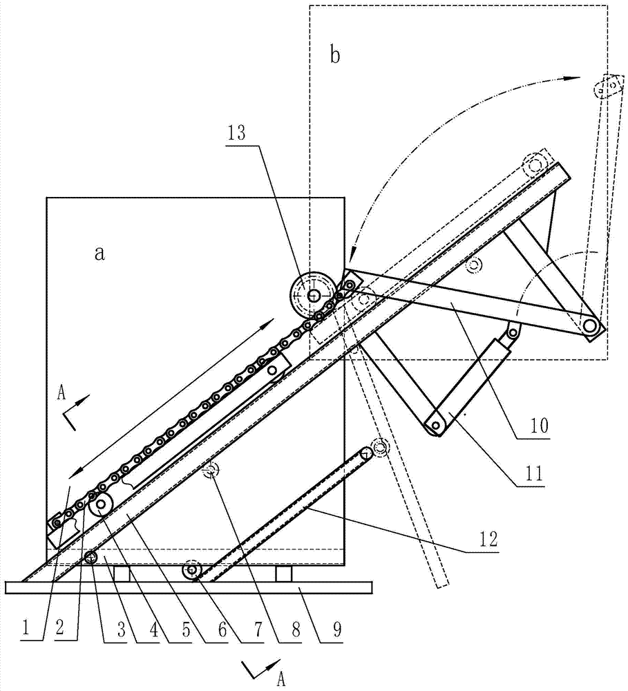
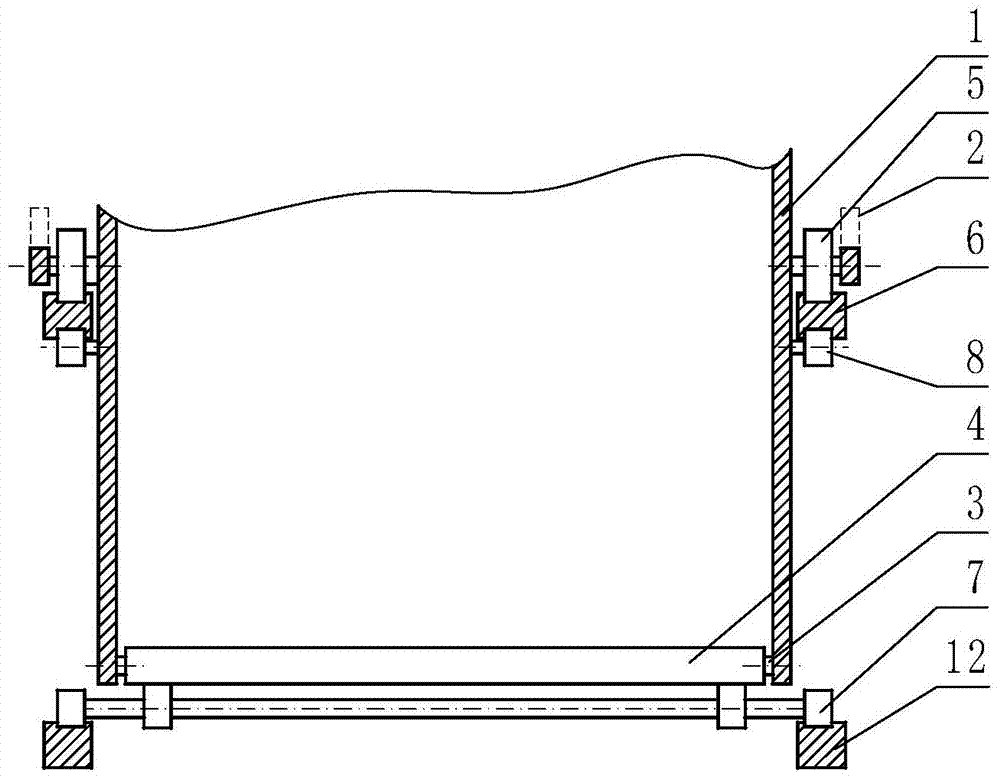
[0018] Embodiment 1: with reference to attached Figure 1-Figure 2 , is a structural schematic diagram of Embodiment 1 of the present invention, including a frame 9 that travels with the main body, and two groups of rail groups that are inclined upward relative to the ground and parallel to each other on different horizontal planes up and down are arranged on the frame 9, that is, the rails A6 and track B12, and the track group at the lower part, that is, track B12, is shorter than the track group at the upper part, that is, track A6, and the upper track group, that is, track A6, is provided with a material box, which contains at least Four side plates 1 and a bottom plate 4 constitute the box body. The bottom plate 4 is a movable plate and is hinged on the side plate 1 of the material box through the pin shaft 3. There are two sets of rollers between the side plates 1 on the left and right sides of the material box and the track A6. A5, each group consists of 3 rollers, the t...

Embodiment 2

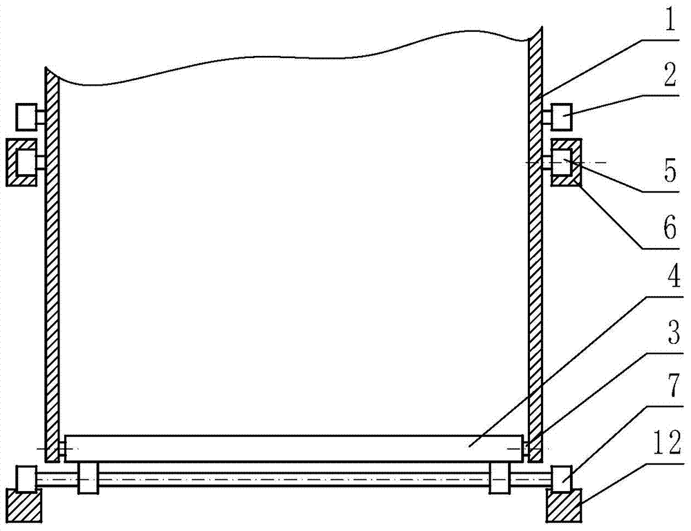
[0019] Embodiment 2: refer to image 3 , is a schematic structural diagram of Embodiment 2 of the present invention. Compared with Embodiment 1, the difference of this embodiment is:

[0020] The upper track group, that is, the track of track A6 is a groove, and the roller A5 between the side plate 1 on the left and right sides of the material box and the track A6, each group consists of 2 rollers, and the roller A5 is in the groove of track A6 , it can not only ensure that the box rises or returns to run according to the track, but also prevents the box from derailing during the process of rising or returning, and the structure is simpler.

Embodiment 3

[0021] Embodiment 3: refer to Figure 4 , is a structural schematic diagram of Embodiment 3 of the present invention. Compared with Embodiment 1, the difference of this embodiment is that the driving mechanism 11 is a hoist, the driving end of the hoist is connected to the traction rope 2, and the positioning of the traction rope 2 Mechanism 13 is a sheave, and the corresponding traction rope 2 is a steel wire rope.


PUM


Abstract

The invention discloses a collecting device of an agricultural harvesting machine. The collecting device comprises a rack (9) moving along with a main machine body. Two sets of rails which incline upwards are arranged on the rack (9). A material box at least comprises side plates (1) and a bottom plate (4), and at least the bottom plate (4) is a movable plate and is hinged to the side plates (1) of the material box through pin shafts (3). At least two sets of rollers A (5) are arranged between the side plates (1) of the material box and the rail A (6), rollers B (7) are arranged between the bottom plate (4) and the rail B (12). A traction mechanism is arranged between the rack (9) and the material box (1) to enable the material box (1) to move along the tracks of the rail A (6). Compared with the prior art, a low working gravity center can be maintained in picking or collecting operation, so that stability under the condition of large bearing capacity is guaranteed; when being unloaded, materials can be unloaded to a high platform, for example, the materials are directly unloaded to a transportation carriage, the process of material pouring can be omitted, and the operation process is greatly simplified, so that the operation efficiency is improved, and the production cost is lowered.

Description

technical field [0001] The invention relates to a mechanical device, in particular to a material collecting device of an agricultural harvesting machine. Background technique [0002] In various material collection machines, objects are often picked up and collected during travel or movement, such as picking up and collecting scattered objects from the ground and other similar places, and then dumping them to designated places, such as the recycling of broken mulch in agricultural production , the harvest of crops such as cotton, tomato, potato, sweet potato, etc., all there is the situation of picking up and concentrating. [0003] In the process of operation, because the machine is moving, the carrying capacity of the general material box is large and heavy, and the center of gravity of the material box should be as low as possible to increase the carrying capacity and make the stability of the whole equipment better, but at the same time It also brings another problem, t...

Claims


Application Information

Patent Timeline
Patent Type & Authority Patents(China)
IPC IPC(8): B65G65/34B65D88/02B65D90/00
Inventor 王士国王能勇缑海啸康建明纪超
Owner XINJIANG ACADEMY OF AGRI & RECLAMATION SCI
Why Eureka
Try Eureka