
Gasifier device and method for gasifying pulverized coal by simultaneously feeding gasifying agents from top burner and furnace body layer by layer and strongly rotating gasifying agents

A technology of gasification agent and gasification furnace, which is applied in the field of coal gasification, and can solve the problems of uneven slag hanging on the wall of the gasification furnace, burning and corrosion of the inner wall of the gasification furnace, etc.

Inactive Publication Date: 2015-11-25
HARBIN INST OF TECH
View PDF6 Cites 8 Cited by
  • Summary
  • Abstract
  • Description
  • Claims
  • Application Information

AI Technical Summary

Problems solved by technology

[0003] The purpose of the present invention is to provide a gasification agent that is fed into the strong rotary pulverized coal gasifier device simultaneously from the top burner and the furnace body in layers, so as to solve the problem of uneven slag hanging on the wall surface of the gasifier in the prior art, which causes the gasifier Inner wall surface burning, corrosion and other problems

Method used


Image

  • Gasifier device and method for gasifying pulverized coal by simultaneously feeding gasifying agents from top burner and furnace body layer by layer and strongly rotating gasifying agents
  • Gasifier device and method for gasifying pulverized coal by simultaneously feeding gasifying agents from top burner and furnace body layer by layer and strongly rotating gasifying agents
  • Gasifier device and method for gasifying pulverized coal by simultaneously feeding gasifying agents from top burner and furnace body layer by layer and strongly rotating gasifying agents

Examples


specific Embodiment approach 1

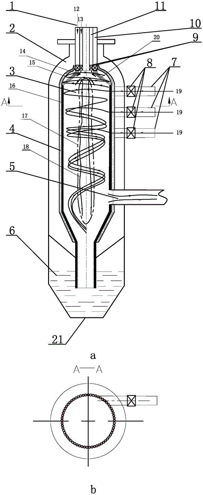
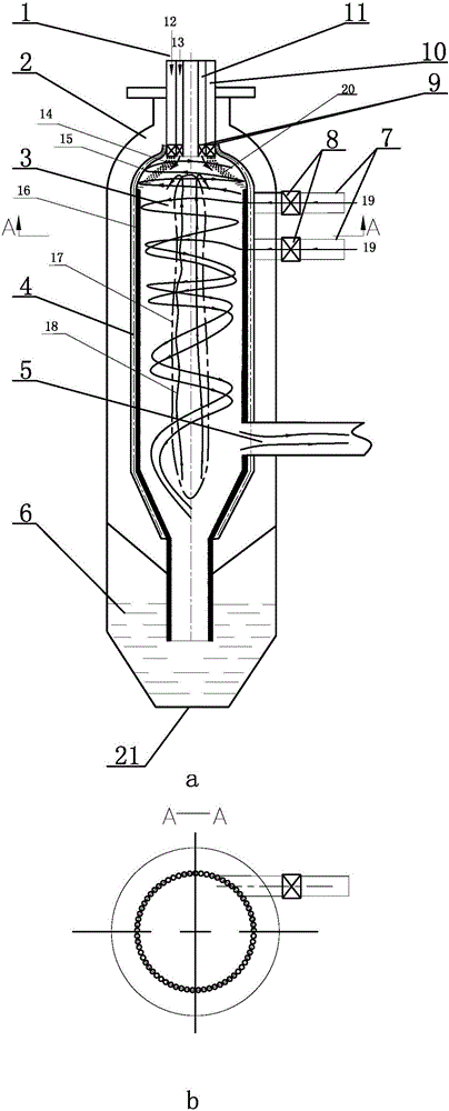
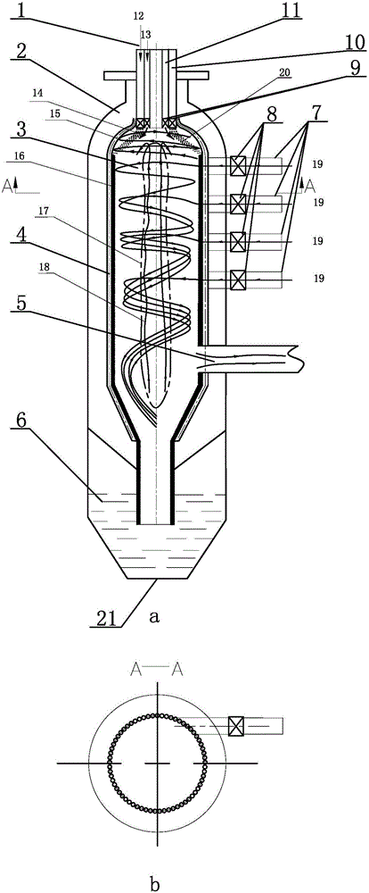
[0025] Specific implementation mode one: combine Figure 1 to Figure 3 Describe this embodiment, a kind of gasification agent described in this embodiment is fed into the strong rotating pulverized coal gasifier simultaneously from the top burner and the furnace body layered Furnace 3, water wall 4, synthesis gas channel 5, slag pool 6, multiple gasification agent nozzles 7, multiple gas flow regulating valves 8, swirl blades 9, pulverized coal channel 10 and gasification agent channel 11, gasifier The body 2 is composed of a hemisphere and a cylinder. The water-cooled wall 4 is installed in the gasification furnace body 2. The water-cooled wall 4 is composed of a plurality of vertical circular tubes arranged side by side. The gasification furnace 3 is a rotary wall surrounded by the water-cooled wall 4. body, the slag pool 6 is located at the bottom of the gasification furnace body 2, the syngas channel 5 is inserted in the lower part of the gasification furnace body 2, and a...

specific Embodiment approach 2

[0026] Specific implementation mode two: combination figure 1 To illustrate this embodiment, a gasification agent described in this embodiment is fed into the strong rotary pulverized coal gasification furnace device simultaneously from the top burner and the furnace layer. The multiple gasification agent nozzles 7 refer to three gasification agents Spout 7. Other components and connections are the same as those in the first embodiment.

specific Embodiment approach 3

[0027] Specific implementation mode three: combination figure 2 To illustrate this embodiment, a gasification agent described in this embodiment is simultaneously fed into a plurality of gasification agent nozzles 7 of a strong rotary pulverized coal gasifier device from the top burner and the furnace body in layers, referring to two gasification agents Spout 7. Other components and connections are the same as those in the first embodiment.

[0028] Specific implementation mode four: combination image 3 To illustrate this embodiment, a gasification agent described in this embodiment is fed into the strong rotary pulverized coal gasification furnace device at the same time from the top burner and the furnace layer. The multiple gasification agent nozzles 7 refer to four gasification agents Spout 7.

[0029] Specific implementation mode five: combination Figure 1 to Figure 3 To illustrate this embodiment, a gasification agent described in this embodiment is simultaneously...


PUM


Abstract

The invention relates to a gasifier and a gasification method and in particular relates to a gasifier device and method for gasifying pulverized coal by simultaneously feeding gasifying agents from a top burner and a furnace body layer by layer and strongly rotating the gasifying agents, aiming to solve the problem in the prior art that slag adheres to the walls of gasifiers non-uniformly, thus causing burning loss and corrosion of inner walls of the gasifiers. The gasifier device is characterized in that a plurality of gasifying agent nozzles are uniformly formed in the upper part of a gasifier body from top to bottom in sequence; nozzle centers of the plurality of gasifying agent nozzles are in a same vertical line vertical to the horizontal plane; a pulverized coal burner is installed at the top of the gasifier body; a gasifying agent channel with a ring-shaped cross section and a pulverized coal channel with a ring-shaped cross section are arranged in the pulverized coal burner; swirl vanes are arranged at the ends, near fire, of the gasifying agent channel and the pulverized coal channel; and a gas flow control valve is arranged on each gasifying agent nozzle. The gasifier device and the method belong to the field of coal gasification.

Description

technical field [0001] The invention relates to a gasification furnace and a gasification method, in particular to a device and a gasification method for simultaneously feeding a gasification agent into a strong rotating pulverized coal gasification furnace from a top burner and a furnace body in layers, and belongs to the field of coal gasification. Background technique [0002] Coal gasification technology is an efficient and clean clean coal technology. The current coal gasification technology is mainly divided into four categories: moving bed gasification, fluidized bed gasification, entrained flow gasification and molten bed gasification. Among them, entrained bed gasification technology has become the main development direction of coal gasification technology due to its advantages of high gasification intensity, large production capacity and high carbon conversion rate. Entrained bed gasification has two main features. One is the high operating temperature, about 1300...

Claims


Application Information

Patent Timeline
IPC IPC(8): C10J3/48C10J3/50
Inventor 李争起陈智超曾令艳王浩鹏刘晓英蒋炳坤朱群益秦裕琨
Owner HARBIN INST OF TECH
Learn More