Construction method for underwater reinforced concrete composite pile of cast-in-situ support of concrete ballast box beam of cable-stayed bridge

A technology of concrete ballast and box girder cast-in-place, which is applied in the direction of bridges, bridge construction, erection/assembly of bridges, etc. It can solve the problems of high construction costs, difficult demolition, and high safety risks of flood crossing, and achieves simple erection and safe support Improvement, the effect of strong flood resistance

Active Publication Date: 2015-11-25
CHINA RAILWAY GUANGZHOU ENG GRP CO LTD +1
View PDF6 Cites 11 Cited by
  • Summary
  • Abstract
  • Description
  • Claims
  • Application Information

AI Technical Summary

Problems solved by technology

[0007] In order to solve the above problems, the present invention provides a construction method of steel-concrete composite piles in water for concrete ballasted box girder cast-in-place supports of cable-stayed bridges, which successfully solves the problems of high construction costs, difficult demolition, and safety risks of flood crossing in water for ballasted box girder supports high problem

Method used


Image

  • Construction method for underwater reinforced concrete composite pile of cast-in-situ support of concrete ballast box beam of cable-stayed bridge
  • Construction method for underwater reinforced concrete composite pile of cast-in-situ support of concrete ballast box beam of cable-stayed bridge
  • Construction method for underwater reinforced concrete composite pile of cast-in-situ support of concrete ballast box beam of cable-stayed bridge

Examples


Embodiment Construction

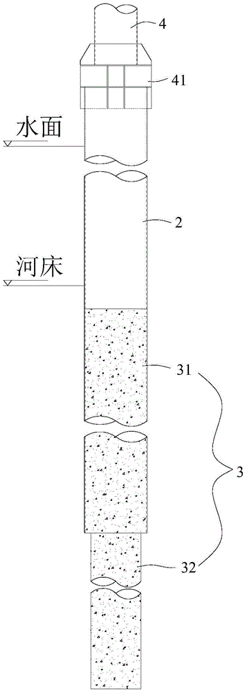
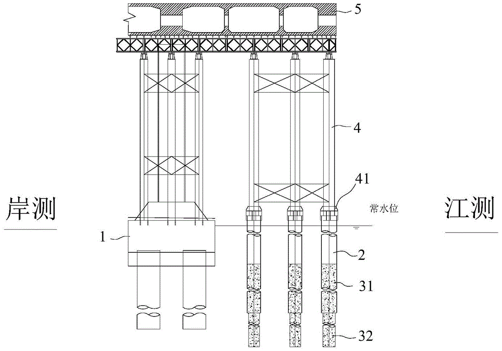
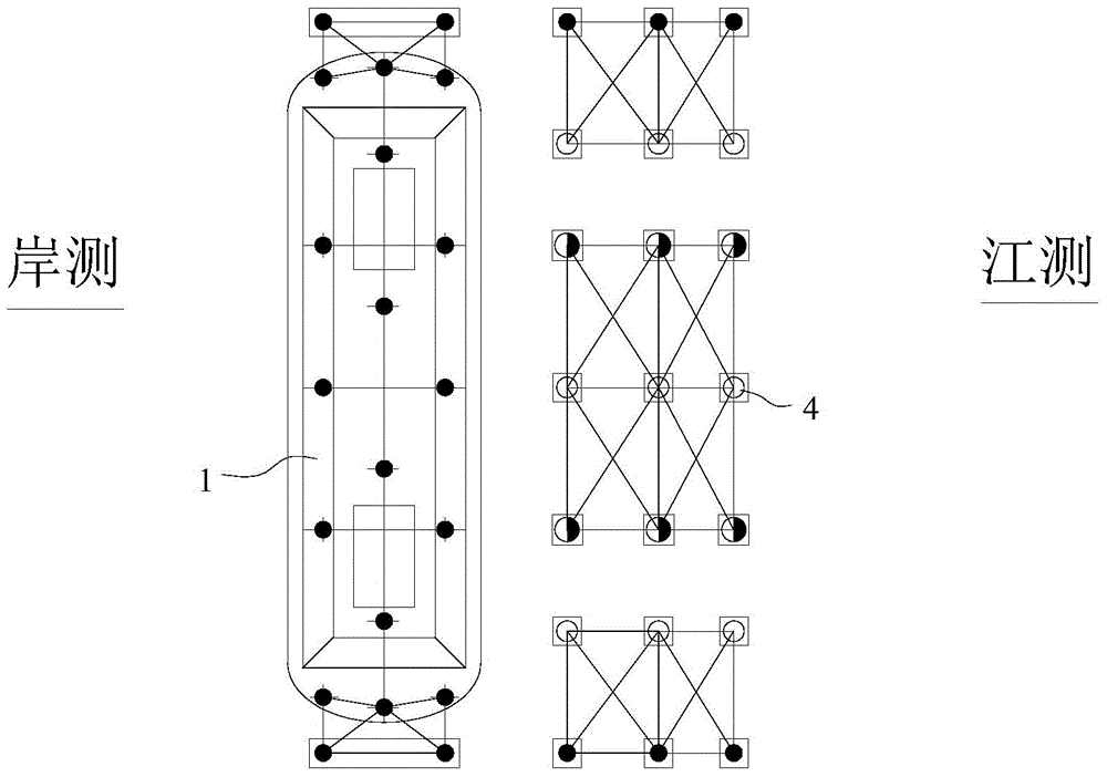
[0032] refer to Figure 1 to Figure 3 , which shows the specific structure of the preferred embodiment of the present invention. The structural features of each element of the present invention will be described in detail below, and if there is a description of the direction (up, down, left, right, front and back), it is based on figure 2 The shown structure is a reference description, but the actual use direction of the present invention is not limited thereto.

[0033] The invention provides a construction method of steel-concrete composite piles in water for cast-in-place supports of concrete ballasted box girders of cable-stayed bridges, comprising the following steps:

[0034] S10. Insert a number of steel casings on the side of the auxiliary pier of the cable-stayed bridge away from the shore. When inserting, a small crawler crane stands on the top surface of the auxiliary pier cap 1 and hangs a small vibrating hammer in the direction of the mid-span to insert steel ca...


PUM


Abstract

The invention discloses a construction method for an underwater reinforced concrete composite pile of a cast-in-situ support of a concrete ballast box beam of a cable-stayed bridge. The construction method comprises the steps that steel pile casings are inserted and driven; primary connecting systems are arranged around the steel pipe casings, and steel face plates are laid on the primary connecting systems; a percussion drill is used for carrying out drilling on the interiors of the steel pipe casings downwards, and after designed elevation is achieved in a drilling manner, steel reinforcement cage mounting, guide pipe tripping in and hole clearing work are carried out on formed holes; concrete is poured in the formed holes to the designed elevation to form concrete piles, and the concrete piles comprise steel concrete transition connecting portions in the bottom ends of the steel pile casings and drilling and pouring portions stretching out of the bottom ends of the steel pile casings; and the rest of steel pile casings are constructed in sequence, and after all the steel pipe casings are constructed, secondary connecting systems, bridge transverse distribution beams, bridge longitudinal bailey beam sets, lumps of wood and timber formworks are arranged on support steel pipes at the tops of the steel pile casings, and are demounted after construction of the concrete ballast box beam is finished. The problems that an underwater support foundation of the ballast box beam is high in construction cost, demounting is hard, and flood crossing safety risks are high are successfully solved.

Description

technical field [0001] The invention is used in the technical field of bridge construction, and in particular relates to a construction method for a steel-concrete composite pile in water of a concrete ballast box girder cast-in-place support of a cable-stayed bridge. Background technique [0002] With the large-scale construction of my country's highway and railway expressway network, a large number of bridges across rivers, rivers and seas have been built, and cable-stayed bridges are one of the most common types of long-span bridges. At the same time, long-span cable-stayed bridges In order to increase its own span, the main girder is generally in the form of a steel girder, and the side span usually needs to be equipped with a concrete ballast box girder for counterweight. As the ballast structure of the bridge, the ballast box girder itself must have sufficient rigidity, strength and weight. The ballast box girder has a large area and is prone to cracks. The setting req...

Claims


Application Information

Patent Timeline
Patent Type & Authority Applications(China)
IPC IPC(8): E01D21/00E02D27/52
Inventor 周文冯朝军王保贺清华缪晨辉马超郭磊王友顺
Owner CHINA RAILWAY GUANGZHOU ENG GRP CO LTD
Why Eureka
Try Eureka