
Wall face tile pavement structure

A wall brick and pavement technology, which is applied in building structure, covering/lining, construction, etc., can solve the problems of prolonging the construction period, falling off of decorative bricks, and high difficulty of construction, so as to prolong the service life and safety, and improve the smoothness , Improve the effect of aesthetics

Inactive Publication Date: 2015-11-25
苏州苏明装饰股份有限公司
View PDF6 Cites 0 Cited by
  • Summary
  • Abstract
  • Description
  • Claims
  • Application Information

AI Technical Summary

Problems solved by technology

[0002] In the decoration project, wall tiles, vitrified tiles, etc. are common construction projects. Usually, the cement mortar wet paste process is used. The cement mortar is mixed with 801 glue as the bonding layer, and the base layer of the brick wall is wetted with water to start paving. Due to the drying shrinkage of the mortar bonding layer, this process is prone to quality problems such as hollowing and dry cracking with the decorative brick surface layer, which will affect the bonding strength of the wall decorative bricks and cause the decorative bricks to fall off in severe cases
[0003] In addition, there are brick joints between adjacent decorative bricks, which are usually filled with caulking agent, but traditional paving methods are prone to uneven brick joints and uneven brick surfaces, which will affect the aesthetics of the entire wall. The paving process has high requirements on the technical level of the construction personnel themselves, and the paving efficiency is low, which prolongs the construction period
At the same time, after laying the decorative tiles, if it is necessary to change or increase the wire routing in the future, it is necessary to destructively pry up the tiles and rewire them. surface aesthetics

Method used


Image

  • Wall face tile pavement structure
  • Wall face tile pavement structure
  • Wall face tile pavement structure

Examples


Embodiment 1

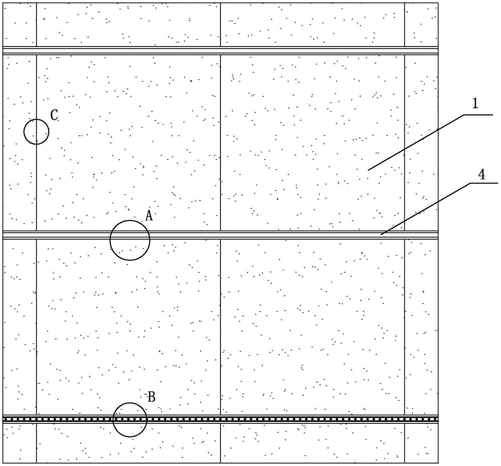
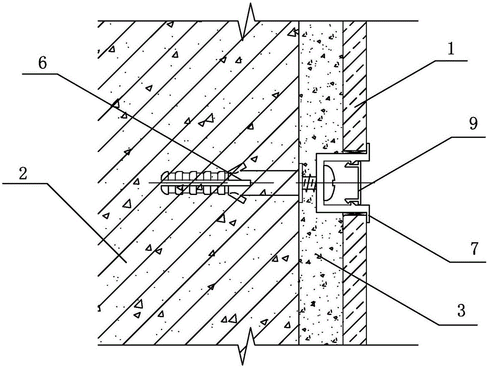
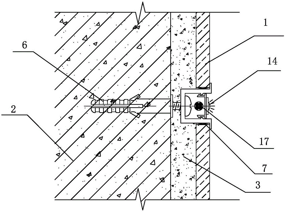
[0027] Embodiment one: see Figure 1~5 As shown, a wall brick pavement structure includes a cement mortar layer 3 between the brick 1 and the wall 2, a plurality of support structures 4, and the support structures 4 are distributed on the upper and lower adjacent In the brick joints between the facing bricks 1, each of the support structures 4 includes a concave base bar 5 and a plurality of fixing bolts 6, and the concave base bar 5 is arranged along the horizontal direction where the facing bricks 1 are laid. And the facing bricks on the corresponding upper and lower sides are respectively provided with flanging 7, and the facing bricks 1 are positioned at the inner side of the flanging 7, and the end faces of the upper and lower bricks are against the sides of the concave base bar 5, and between the two Spacers 8 are provided between them; the fixing bolts 6 are expansion bolts, which are arranged at intervals in the concave base bar 5 at intervals of 200mm-400mm (preferabl...


PUM


Abstract

The invention discloses a wall face tile pavement structure. The wall face tile pavement structure comprises a cement mortar layer located between face bricks and a wall body and is characterized by further comprising a plurality of support structures, the support structures are distributed in brick joints among the upper and lower adjacent face bricks, each support structure comprises a concave base strip and a plurality of fixed bolts, the concave base strips are arranged in the horizontal direction of face brick pavement, the face bricks corresponding to the upper side and the lower side are respectively provided with turnup edges, the face bricks are located on the inner sides of the turnup edges, and the end faces of the upper face bricks and the lower face bricks abut against the lateral sides of the concave base strips. The fixed bolts are arranged in the concave base strips at intervals, and the tail ends of the fixed bolts penetrate through the concave base strips to be fixed in the wall body. The wall face tile pavement structure provides a metal frame supporting force for face brick pavement through the arranged support structures, does not shed even if the cement mortar layer is invalid, the strength and firmness of face brick pavement are improved, and meanwhile overall attractiveness and decorativeness are improved.

Description

technical field [0001] The invention relates to the technical field of indoor wall surface decoration, in particular to a wall brick pavement structure. Background technique [0002] In the decoration project, wall tiles, vitrified tiles, etc. are common construction projects. Usually, the cement mortar wet paste process is used. The cement mortar is mixed with 801 glue as the bonding layer, and the base layer of the brick wall is wetted with water to start paving. , due to the drying shrinkage of the mortar bonding layer, this process is prone to quality problems such as hollowing and dry cracking with the decorative brick surface layer, which will affect the bonding strength of the wall decorative bricks, and in severe cases will cause the decorative bricks to fall off. [0003] In addition, there are brick joints between adjacent decorative bricks, which are usually filled with caulking agent, but traditional paving methods are prone to uneven brick joints and uneven bric...

Claims


Application Information

Patent Timeline
Patent Type & Authority Applications(China)
IPC IPC(8): E04F13/21E04F13/074
Inventor 顾正浩
Owner 苏州苏明装饰股份有限公司
Learn More