
High-angle well/horizontal well formation resistivity anisotropy correcting method

A technology of formation resistivity and anisotropy, applied in wellbore/well components, earth-moving drilling, etc., can solve discrete, log curve continuity and heterogeneity violations, and cannot use logging data to explain point by point And other issues

Active Publication Date: 2015-11-25
BC P INC CHINA NAT PETROLEUM CORP +1
View PDF7 Cites 17 Cited by
  • Summary
  • Abstract
  • Description
  • Claims
  • Application Information

AI Technical Summary

Problems solved by technology

The correction chart is made according to theoretical calculation or experimental results. All parameters in the chart represent the average characteristics of each sampling point in a layer. The correction result is only to increase or decrease the resistivity of the target layer in high-deviation / horizontal wells by one The same ratio is contrary to the unique continuity and heterogeneity of the logging curve, and only has theoretical qualitative interpretation and reference value, and cannot be applied to the point-by-point interpretation of actual logging data
The automatic correction method is based on the plate method, which is based on the reasonable sampling and reading value fitting of the curves in the calibration plate, using standardized formulas to replace a large number of plate curves, and compiling a correction processing program library to realize automatic computer correction. The number of anisotropic plate correction is small and relatively discrete, which is not completely in line with the actual situation. It has great regional characteristics, and the adaptability of the correction method is poor.

Method used


Image

  • High-angle well/horizontal well formation resistivity anisotropy correcting method
  • High-angle well/horizontal well formation resistivity anisotropy correcting method
  • High-angle well/horizontal well formation resistivity anisotropy correcting method

Examples


Embodiment Construction

[0041] The present invention will be further described in detail below in conjunction with specific embodiments, which are explanations of the present invention rather than limitations.

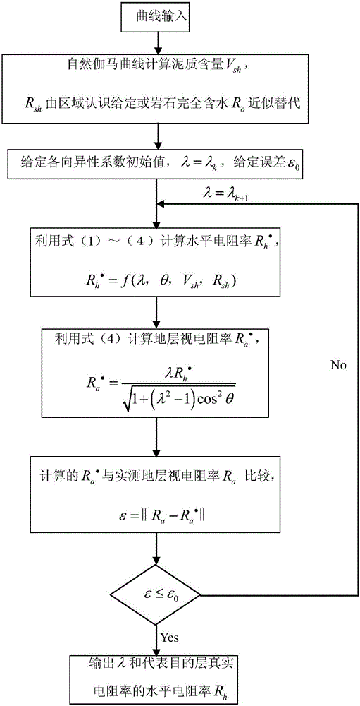
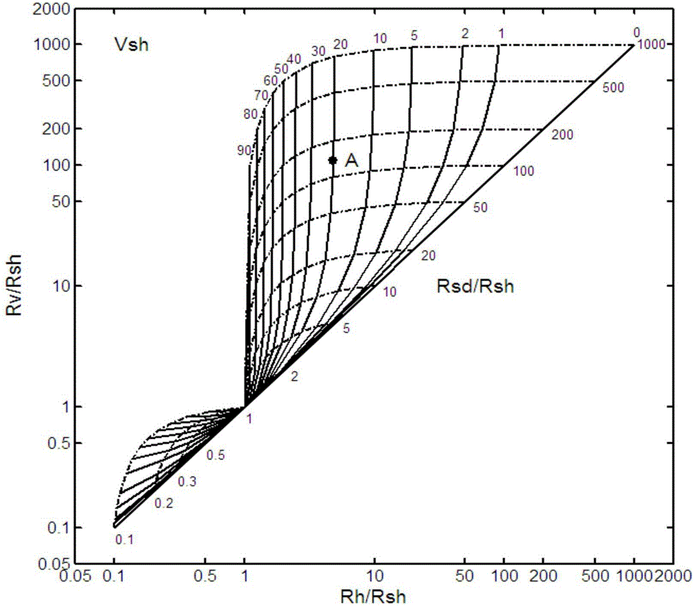
[0042] In the present invention, formation resistivity anisotropy can be divided into macroscopic anisotropy and microscopic anisotropy, and the parameters describing formation resistivity anisotropy mainly include, horizontal resistivity R h , vertical resistivity R v and the resistivity anisotropy coefficient λ. In highly deviated / horizontal wells, the formation resistivity R measured by the tool a is the horizontal resistivity R h and vertical resistivity R v comprehensive reflection.

[0043] When the wellbore trajectory of the horizontal well is closer to the formation layer, that is, the distance between the wellbore trajectory of the horizontal well and the formation layer is less than the detection depth of the logging tool, or intersects with the formation layer, the logging tool...


PUM


Abstract

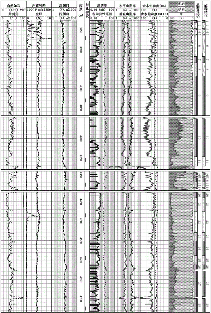
The invention provides a high-angle well / horizontal well formation resistivity anisotropy correcting method. The method comprises the following steps of: 1, building a horizontal and vertical resistivity interpretation chart according to various parameters of resistivity macroscopic anisotropy and microscopic anisotropy and the mutual relationship among the parameters; and 2, determining the total macroscopic and microscopic anisotropy coefficient of the formation resistivity by an iterative algorithm according to the analysis on the horizontal and vertical resistivity interpretation chart, so that the formation resistivity anisotropy correction is performed, and the horizontal resistivity representing the real resistivity of a target layer is worked out. The method effectively solves the problems that a chart method cannot reflect the heterogeneity of a reservoir and is not suitable for level-by-level interpretation of logging information; and due to small correcting chart number and high dispersion degree, an automatic correcting method does not completely conform to the practical conditions, and has the defects of great regional limitation and the like. The high-angle / horizontal well formation resistivity anisotropy correcting method is very suitable for level-by-level interpretation of the logging information; fast interpretation in production can be timely served and met; and good application prospects are realized.

Description

technical field [0001] The invention relates to the technical field of highly deviated / horizontal well logging interpretation and evaluation technology, in particular to a highly deviated / horizontal well formation resistivity anisotropy correction method. Background technique [0002] With the rapid development of the petroleum industry, the oil and gas reservoirs to be explored and developed are becoming more and more complex. Horizontal well technology has been favored all over the world for its advantages of high return on investment and wide application range. Of the types of wells drilled in the future, the majority will be horizontal wells. However, horizontal wells are different from vertical wells, and the logging response of horizontal wells is seriously affected by the geometry of the formation near the wellbore, measurement orientation, abnormal invasion profile, tool eccentricity and anisotropy caused by gravity, etc. Before evaluating the formation of horizontal...

Claims


Application Information

Patent Timeline
IPC IPC(8): E21B49/00
Inventor 罗少成成志刚林伟川肖飞杨智新高浩锋唐冰娥杨超超张峰
Owner BC P INC CHINA NAT PETROLEUM CORP
Learn More