Eureka AIR delivers breakthrough ideas for toughest innovation challenges, trusted by R&D personnel around the world.

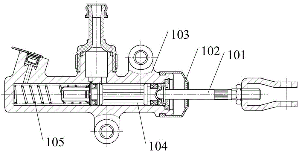
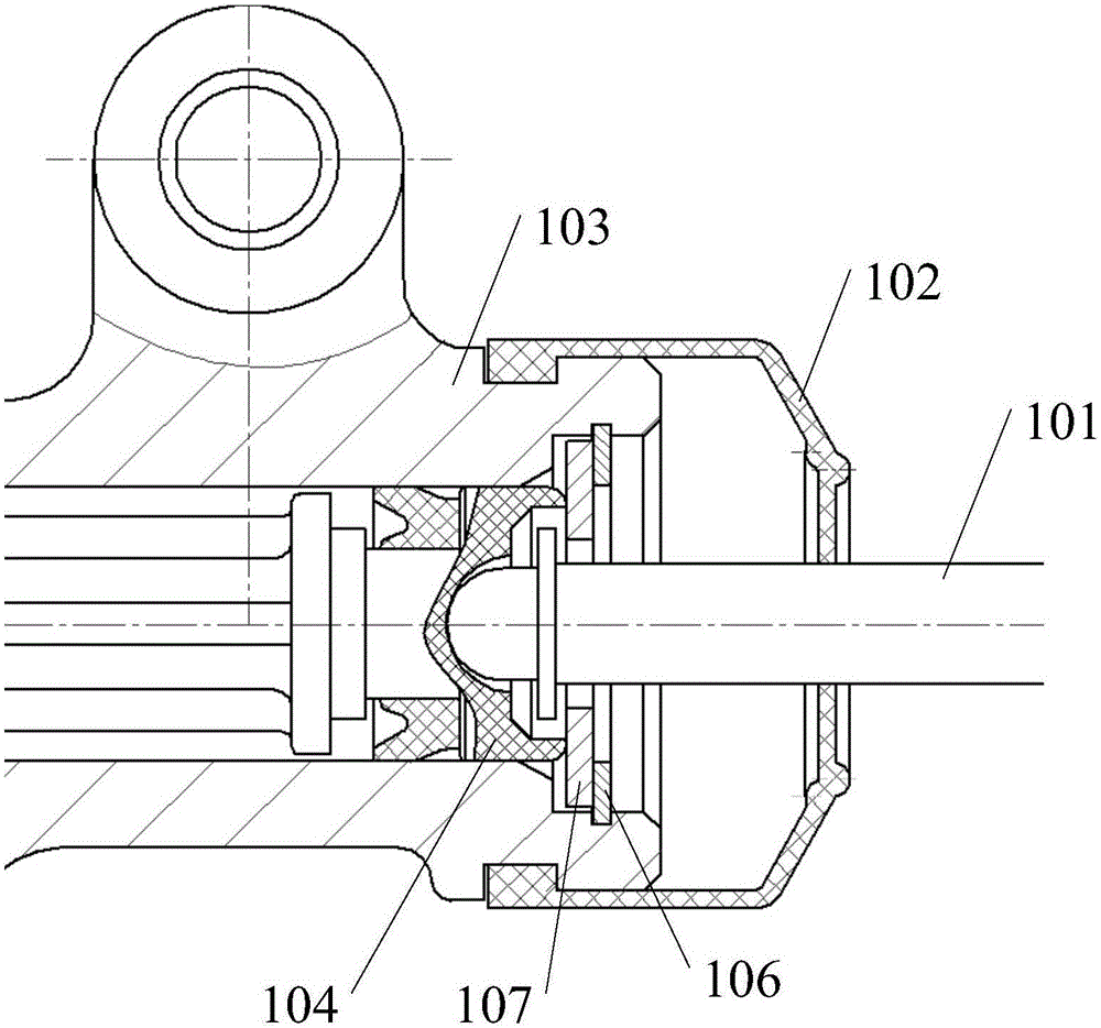
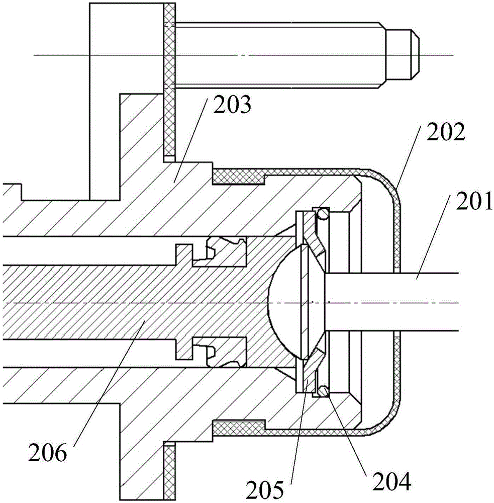
Clutch master cylinder structure

A clutch master cylinder and push rod technology, which is applied in clutches, fluid-driven clutches, non-mechanical drive clutches, etc., can solve the problems of easy wear of the piston 104 and the cylinder body 103, increased movement resistance of the piston 104, and shortened service life of the clutch master cylinder and other issues to achieve the effect of guaranteed performance, reduced friction, and reduced radial pressure

Inactive Publication Date: 2015-11-25
ANHUI JIANGHUAI AUTOMOBILE GRP CORP LTD
View PDF5 Cites 1 Cited by
  • Summary
  • Abstract
  • Description
  • Claims
  • Application Information

AI Technical Summary

Problems solved by technology

[0004] Existing clutch master cylinder structure leaves gap between the central hole of flat stop ring 107 and master cylinder push rod 101, when return spring 105 is in free state, master cylinder push rod 101 can be in spherical groove due to itself The effect of gravity will swing, so that the axis of the master cylinder push rod 101 and the axis of the cylinder body 103 form an angle. If the angle is too large, after the clutch master cylinder is installed, the master cylinder push rod 101 will push the piston. The angle between the direction of the force and the axis of the cylinder block 103 is too large, causing the radial pressure between the piston 104 and the inner wall of the cylinder block 103 to increase, and the movement resistance of the piston 104 to increase, which affects the performance of the clutch; and the increase in the radial pressure makes the piston 104 and cylinder block 103 are easy to wear and tear, shortening the service life of the clutch master cylinder

Method used


Image

  • Clutch master cylinder structure
  • Clutch master cylinder structure
  • Clutch master cylinder structure

Examples


Embodiment Construction

[0026] In order to make the object, technical solution and advantages of the present invention clearer, the present invention will be further described in detail below in conjunction with the accompanying drawings and embodiments. It should be understood that the specific embodiments described here are only used to explain the present invention, not to limit the present invention.

[0027] Please refer to Figure 2-Figure 5 , in a specific embodiment, the structure of the clutch master cylinder provided by the present invention includes a master cylinder push rod 201 that pushes the piston 206 to move and a retaining ring 205 installed at the end of the cylinder body 203 close to the master cylinder push rod 201; One end of the ring 205 close to the piston 203 is provided with a tapered groove 212; the master cylinder push rod 201 includes a push rod body 207 and a ball head, the piston side 209 of the ball head is against the piston 206, and the retaining ring side 208 is pro...


PUM


Abstract

The invention belongs to the technical field of automobile components, and provides a clutch master pump structure. The clutch master pump structure comprises a master pump push rod pushing a piston to move and a check ring installed at the end, close to the master pump push rod, of a cylinder. A conical groove is formed in the end, close to the piston, of the check ring. The master pump push rod comprises a push rod body and a ball head. The piston side of the ball head abuts against the piston. The check ring side is provided with a conical structure matched with the conical groove. The conical structure is inserted in the conical groove. The push rod body penetrates the check ring to be connected to the check ring side. The conical structure is arranged on the master pump push rod, the check ring is provided with the conical groove, and by means of the cooperation of conical surfaces, the master pump push rod is limited and is prevented from swinging; and thus the pressure and friction force between the piston and the cylinder are reduced, abrasion between the piston and the cylinder is reduced, the maser pump push rod moves more smoothly, and the performance of a clutch is guaranteed.

Description

technical field [0001] The invention belongs to the technical field of automobile parts, and in particular relates to a clutch master cylinder structure. Background technique [0002] The clutch master cylinder is the part connected to the clutch pedal and connected to the clutch booster through the oil pipe. When shifting gears, the driver needs to step on the clutch pedal first, the push rod of the clutch master cylinder pushes the piston to increase the oil pressure in the clutch system, and then pushes the separation fork through the push rod of the clutch slave cylinder, the separation fork pushes the release bearing, and the release bearing Push the clutch diaphragm spring, thereby disengaging. [0003] The structure of the existing clutch master cylinder is as follows: Figure 1-Figure 2 As shown, it includes a cylinder block 103, and a piston 104 is inserted into the cylinder block 103 sliding along its axis, and the piston 104 is provided with a spherical groove; i...

Claims


Application Information

Patent Timeline
Patent Type & Authority Applications(China)
IPC IPC(8): F16D25/12
Inventor 邹文迅杨允辉陆静静岳丽姣喻少高陈健
Owner ANHUI JIANGHUAI AUTOMOBILE GRP CORP LTD
Why Eureka
Eureka Blog
Learn More