Eureka AIR delivers breakthrough ideas for toughest innovation challenges, trusted by R&D personnel around the world.

Energy-efficient automobile hydraulic coupler

A hydraulic coupling, high-efficiency and energy-saving technology, applied in the direction of clutches, clutches, fluid clutches, etc., can solve problems such as waste of energy, complicated disassembly, and inconvenient maintenance, so as to improve work efficiency, facilitate disassembly and maintenance, and facilitate assembly and disassembly Effect

Inactive Publication Date: 2015-11-25
TIANJIN PTWIN TECH
View PDF1 Cites 0 Cited by
  • Summary
  • Abstract
  • Description
  • Claims
  • Application Information

AI Technical Summary

Problems solved by technology

[0003] The present invention provides a high-efficiency and energy-saving automobile hydraulic coupler to solve the problems of complicated disassembly, inconvenient maintenance and waste of energy proposed in the above-mentioned background technology

Method used


Image

  • Energy-efficient automobile hydraulic coupler

Examples


Embodiment

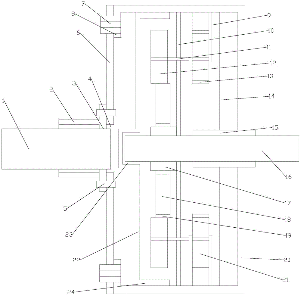
[0017] This embodiment includes a coupler bottom case 20 and a coupler end cover 6, one side of the coupler bottom case 20 is open and the interior is hollow, a fixing plate 8 is arranged at the opening of the coupler bottom case 20, and the coupler end cover 6 and the fixing plate 8 Fixedly connected by bolt 7, a limit sleeve 2 is provided on one side of the coupler end cover 6, the limit sleeve 2 and the coupler end cover 6 are fixedly connected by screws 5, the limit sleeve 2 is provided with a round hole 3, and the coupler The bottom shell 20 is provided with a through groove 4, the limit sleeve 2 is provided with an input shaft 1, and the input shaft 1 passes through the round hole 3, and the coupler bottom shell 20 is provided with a limit baffle 22, and the two ends of the limit baffle 22 are A supporting plate 24 is provided, and the supporting plate 24 is close to the inner wall of the coupler bottom case 20. A recessed part 23 is provided in the middle of the limit ba...


PUM


Abstract

The invention belongs to the technical field of instruments and equipment and particularly relates to an energy-efficient automobile hydraulic coupler. A limit baffle is arranged in a coupler bottom shell. Two ends of the limit baffle are each provided with a support plate, and the support plates are next to the inner wall of the coupler bottom shell. A concave portion is formed in the middle of the limit baffle, and an output shaft is arranged in the concave portion. The top and the bottom of the interior of the coupler bottom shell are each provided with a support column. A fixing sleeve tube is arranged between the support columns and the output shaft and penetrates through the coupler bottom shell. The output shaft is arranged in the fixing sleeve tube. Two sides of the output shaft are each provided with a guide wheel and a pump wheel which are connected through a connection shaft. The two sides of each pump wheel are each provided with a fixing rod. An inner ring is arranged between each guide wheel and the corresponding pump wheel. The output shaft is sleeved with an inner seat ring, and a turbine is arranged between each guide wheel and the inner seat ring.

Description

technical field [0001] The invention belongs to the technical field of instruments and equipment, and in particular relates to a high-efficiency and energy-saving automobile hydraulic coupler. Background technique [0002] The hydraulic coupling is mainly composed of pump wheel, turbine and coupling housing and other components. The pump wheel is connected to the crankshaft of the engine, and the turbine is connected to the driven shaft. There is no mechanical connection between the pump wheel and the turbine, and the power is transmitted by liquid flow between the two. The use of a hydraulic coupling can ensure a smooth start of the car, attenuate the torsional vibration of the drive train, prevent the drive train from being overloaded, and significantly reduce the number of shifts. For example, Chinese patent 201180027843.5 discloses a hydraulic coupler, which has: a pump impeller and a turbine impeller , which form a ring-shaped working chamber filled with working medium...

Claims


Application Information

Patent Timeline
IPC IPC(8): F16D33/00
Inventor 蔡元学姜春香
Owner TIANJIN PTWIN TECH
Why Eureka
Eureka Blog
Learn More