Agitator and shaft end sealing structure thereof and shaft end sealing structure installation method

A shaft end seal and agitator technology, which is applied in the direction of engine seals, mechanical equipment, engine components, etc., can solve the problems of lack of special tooling and equipment, damage to important parts such as main shaft, and elongated shaft end installation and maintenance cycle, etc., to reduce Adverse effects, the effect of improving the speed of maintenance, and the speed of installation and removal

Active Publication Date: 2015-11-25
ZOOMLION HEAVY IND CO LTD
View PDF6 Cites 5 Cited by
  • Summary
  • Abstract
  • Description
  • Claims
  • Application Information

AI Technical Summary

Problems solved by technology

[0006] When repairing the failed parts of the shaft end of the mixer, it is necessary to dismantle each part on the shaft end one by one. For the parts with interference fit, it is necessary to use methods such as gas cutting and knocking to destroy the parts, which is easy to cause damage to important parts such as the main shaft. After that, new parts are replaced one after another, and the site generally lacks special tooling and equipment for assembly, so it is easy to lengthen the installation and maintenance cycle of the shaft end when repairing the shaft end

Method used


Image

  • Agitator and shaft end sealing structure thereof and shaft end sealing structure installation method
  • Agitator and shaft end sealing structure thereof and shaft end sealing structure installation method
  • Agitator and shaft end sealing structure thereof and shaft end sealing structure installation method

Examples


Embodiment Construction

[0033] The present invention will be described in detail below with reference to the accompanying drawings and examples. It should be noted that, in the case of no conflict, the embodiments in the present application and the features in the embodiments can be combined with each other.

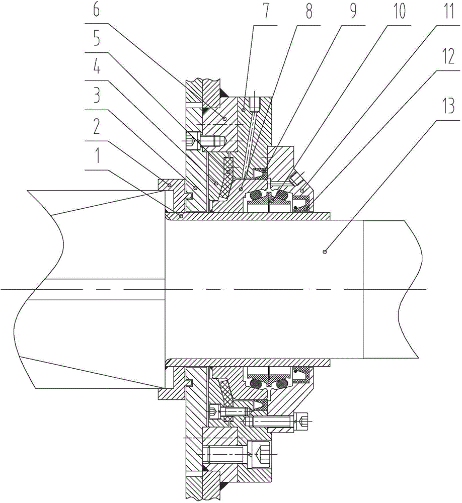
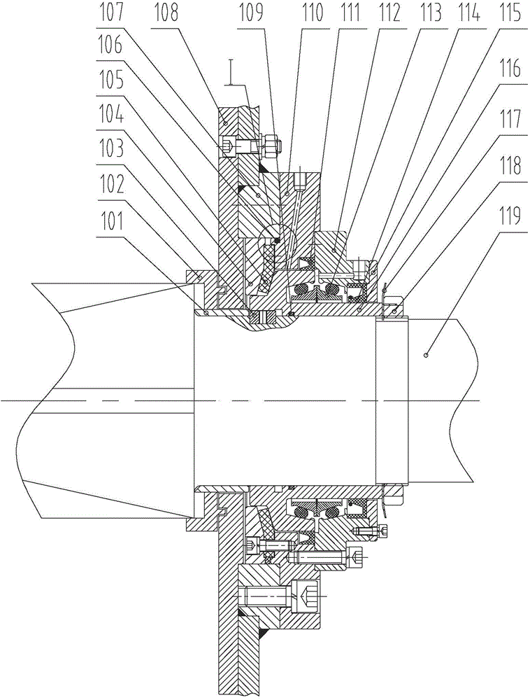
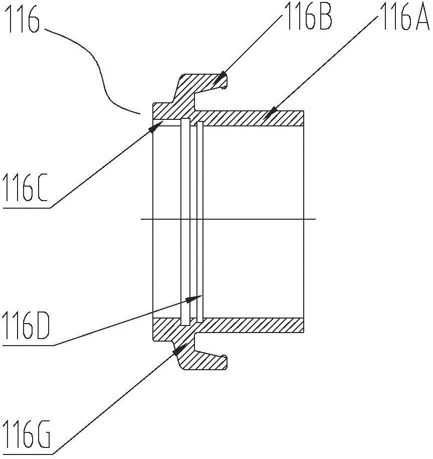
[0034] Such as figure 2 As shown, the present invention provides a shaft end sealing structure of a mixer. The shaft end sealing structure is arranged at the shaft end of the main shaft 119 of the mixer. The shaft end sealing structure includes a sealing module and a non-rotation connecting piece. The sealing module is used to seal the shaft end of the main shaft 119 . The sealing module includes a rotating hub 116 sheathed on the shaft end of the main shaft 119 , the rotating hub 116 is in clearance fit with the main shaft 119 , and the sealing module is detachably connected to the main shaft 119 as a whole. The anti-rotation connecting piece connects the rotating hub 116 of the sealing m...


PUM


Abstract

The invention provides an agitator and a shaft end sealing structure thereof and a shaft end sealing structure installation method. The shaft end sealing structure is arranged at the shaft end of a main shaft of the agitator, and comprises a sealing module and an anti-rotation connecting piece, wherein the sealing module is used for sealing the shaft end of the main shaft, and comprises a rotating hub sleeving the shaft end of the main shaft; the rotating hub and the main shaft are in clearance fit; the sealing module as an integer is detachably connected with the main shaft; and the anti-rotation connecting piece connects the rotating hub of the sealing module to the main shaft so as to enable the rotating hub and the main shaft to synchronously rotate. The sealing module of the shaft end sealing structutre and the main shaft can be assembled together and disassembled repeatedly, the part heating treatment is not needed in installation, and shaft end sealing parts are not needed to be damaged due to disassembly demands, so that the assembly and disassembly time can be shortened, and quick disassembly of the shaft end sealing structure can be realized in repair of the shaft end, so that the repair speed can be increased.

Description

technical field [0001] The invention relates to the field of construction machinery, and more specifically, to a mixer, a shaft end sealing structure thereof, and an installation method for the shaft end sealing structure. Background technique [0002] Concrete mixer is the core component of concrete equipment. The leakage of slurry and water at the shaft end of the concrete mixer will be an unavoidable problem with the long-term use of concrete equipment. Once a slight amount of water slurry penetrates into the shaft end, it will cause the shaft The end of the shaft wears rapidly, which causes the failure of some parts of the shaft end, resulting in the failure of the normal use of the concrete equipment, and even the delay of the on-site project. Therefore, when the shaft end of the concrete mixer is abnormal or fails, how to quickly replace the failed parts of the shaft end and reduce the maintenance cycle of the shaft end is an urgent problem to be solved in the future d...

Claims


Application Information

Patent Timeline
Patent Type & Authority Applications(China)
IPC IPC(8): F16J15/34F16J15/18
CPCF16J15/18F16J15/34
Inventor 李顺郑江才彭明军田淋
Owner ZOOMLION HEAVY IND CO LTD
Why Eureka
Try Eureka