
Visible light auxiliary calibration type laser transmitter and calibration method thereof

A laser transmitter and laser emission technology, applied in the laser field, can solve the problems of low precision, complexity, inconvenient operation, etc., and achieve the effects of convenient operation, scientific rationality and simple structure

Inactive Publication Date: 2015-11-25
NO 60 RES INST OF GENERAL STAFF DEPT PLA
View PDF4 Cites 4 Cited by
  • Summary
  • Abstract
  • Description
  • Claims
  • Application Information

AI Technical Summary

Problems solved by technology

However, due to the invisibility of the infrared laser, the calibration of the laser point and the aiming point of the gun needs to be adjusted with the help of special equipment. This common method is more complicated to use in the field, the accuracy is not high, and it is very inconvenient to operate in the field.

Method used


Image

  • Visible light auxiliary calibration type laser transmitter and calibration method thereof
  • Visible light auxiliary calibration type laser transmitter and calibration method thereof
  • Visible light auxiliary calibration type laser transmitter and calibration method thereof

Examples


Embodiment 1

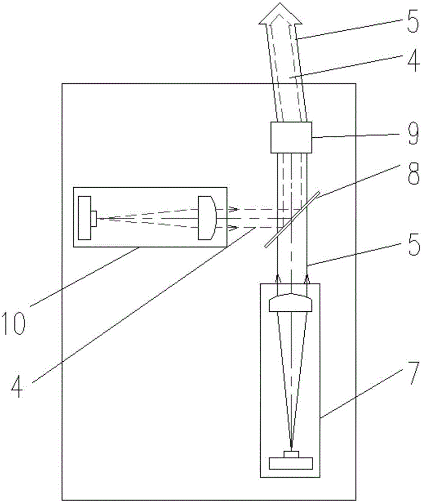
[0027] This embodiment provides a visible light assisted calibration type laser transmitter, the structure is as follows figure 1 , figure 2 As shown, it includes a gun barrel 3, and a laser transmitter 1 installed on the gun barrel 3 through a clamp 2. The laser transmitter 1 is provided with an infrared laser emitting device 7 and a visible laser emitting device 10, and the infrared laser emitting device 7 generates infrared Laser 5, visible laser emitting device 10 produces visible laser 4, laser transmitter 1 is also provided with a beam splitter 8 and an optical path adjustment mechanism 9, infrared laser 5 directly exits the laser transmitter 1 through the optical path adjustment mechanism 9, the visible laser 4 is reflected by the beam splitter 8 into the optical path adjustment mechanism 9 and then exits the laser transmitter 1.

[0028] The visible laser emitting device 10 is set vertically to the infrared laser emitting device 7, and the beam splitter 8 is set at a...

Embodiment 2

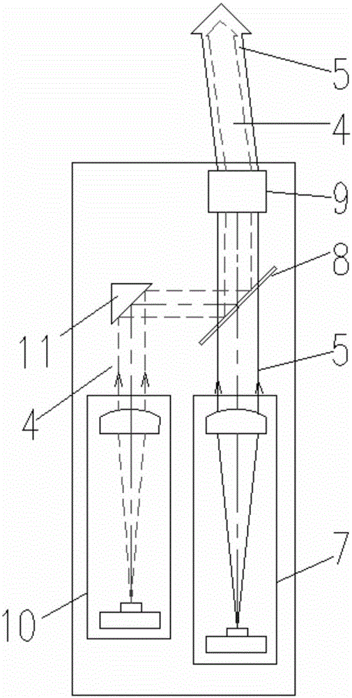
[0031] This embodiment provides a visible light assisted calibration type laser transmitter, the structure is as follows figure 1 , image 3 As shown, it includes a gun barrel 3, and a laser transmitter 1 installed on the gun barrel 3 through a clamp 2. The laser transmitter 1 is provided with an infrared laser emitting device 7 and a visible laser emitting device 10, and the infrared laser emitting device 7 generates infrared Laser 5, visible laser emitting device 10 generates visible laser 4, laser transmitter 1 is also equipped with a beam splitter 8 and an optical path adjustment mechanism 9, infrared laser 5 directly exits the laser transmitter 1 through the optical path adjustment mechanism 9, and visible laser 4 passes through The beam splitter 8 reflects into the optical path adjustment mechanism 9 and then exits the laser transmitter 1 .

[0032] The aforementioned visible laser emitting device 10 is arranged in parallel with the infrared laser emitting device 7. Whe...

Embodiment 3

[0035] This embodiment provides a calibration method for a visible light assisted calibration laser transmitter, such as figure 1 As shown, the specific steps are as follows:

[0036] Install the laser transmitter 1 firmly on the gun barrel 3 through the clamp 2;

[0037] Adjust the optical path adjustment mechanism 9 to synchronously adjust the composite beam of the visible laser 4 and the infrared laser 5, so that the optical axis of the visible laser 4 and the optical axis of the infrared laser 5 are output from the laser transmitter 1 in a common optical axis manner;

[0038] Turn on the visible laser 4 and adjust the visible laser 4 to the aimed target 6 to realize the calibration between the infrared laser 5 and the aiming point of the gun. After the calibration is completed, turn off the visible laser 4;

[0039] Simulate live ammunition shooting of guns for confrontation training.


PUM


Abstract

The invention discloses a visible light auxiliary calibration type laser transmitter. The visible light auxiliary calibration type laser transmitter comprises a gun barrel and a laser transmitter body installed on the gun barrel through a clamp. An infrared laser transmitting device and a visible laser transmitting device are arranged in the laser transmitter body. The infrared laser transmitting device is used for generating infrared lasers. The visible laser transmitting device is used for generating visible lasers. A beam splitter mirror and an optical path adjusting mechanism are further arranged in the laser transmitter body. The infrared lasers are directly emitted out of the laser transmitter body through the optical path adjusting mechanism. The visible lasers are reflected into the optical path adjusting mechanism through the beam splitter mirror and then are transmitted out of the laser transmitter body. The invention further discloses a calibration method for the visible light auxiliary calibration type laser transmitter. The visible light auxiliary calibration type laser transmitter is simple in structure and convenient to operate, and fast calibration of the laser optical axis is achieved during laser countermeasure training through a double-beam structure.

Description

technical field [0001] The invention belongs to the field of laser technology, and relates to a laser transmitter, in particular to a visible light assisted calibration laser transmitter and a calibration method thereof. Background technique [0002] In the field of confrontation training, it is often used to install laser emitting devices on guns, and to simulate actual shooting and hitting effects by emitting infrared lasers to achieve confrontation training. [0003] Due to the differences in the manufacture of laser transmitters and the fact that there are many gun types of weapons, after the laser transmitter is installed on the gun, the laser point and the aiming point do not coincide, and it needs to be calibrated before it can be put into normal combat shooting. However, due to the invisibility of the infrared laser, the calibration of the laser point and the aiming point of the gun needs to be adjusted with the help of special equipment. This common method is more c...

Claims


Application Information

Patent Timeline
Patent Type & Authority Applications(China)
IPC IPC(8): F41A33/02
Inventor 吕战强薛汝东于志芳万华彭海峰赵志立范广健
Owner NO 60 RES INST OF GENERAL STAFF DEPT PLA
Learn More