Robot tool coordinate system correction method

A technology of tool coordinate system and calibration method, applied in the field of calibration of industrial robot tool coordinate system, can solve the problems of error, large error, time-consuming and so on

Active Publication Date: 2015-11-25
SHENZHENSHI YUZHAN PRECISION TECH CO LTD
View PDF5 Cites 39 Cited by
  • Summary
  • Abstract
  • Description
  • Claims
  • Application Information

AI Technical Summary

Problems solved by technology

However, due to the manual assembly of processing tools, the structure of the robot itself, or the tool coordinate system customized by the robot, there will be certain errors, resulting in a certain error in the tool coordinate system of the robot.
Manual corrections are time-consuming, laborious, and have relatively large errors

Method used


Image

  • Robot tool coordinate system correction method
  • Robot tool coordinate system correction method
  • Robot tool coordinate system correction method

Examples


Embodiment Construction

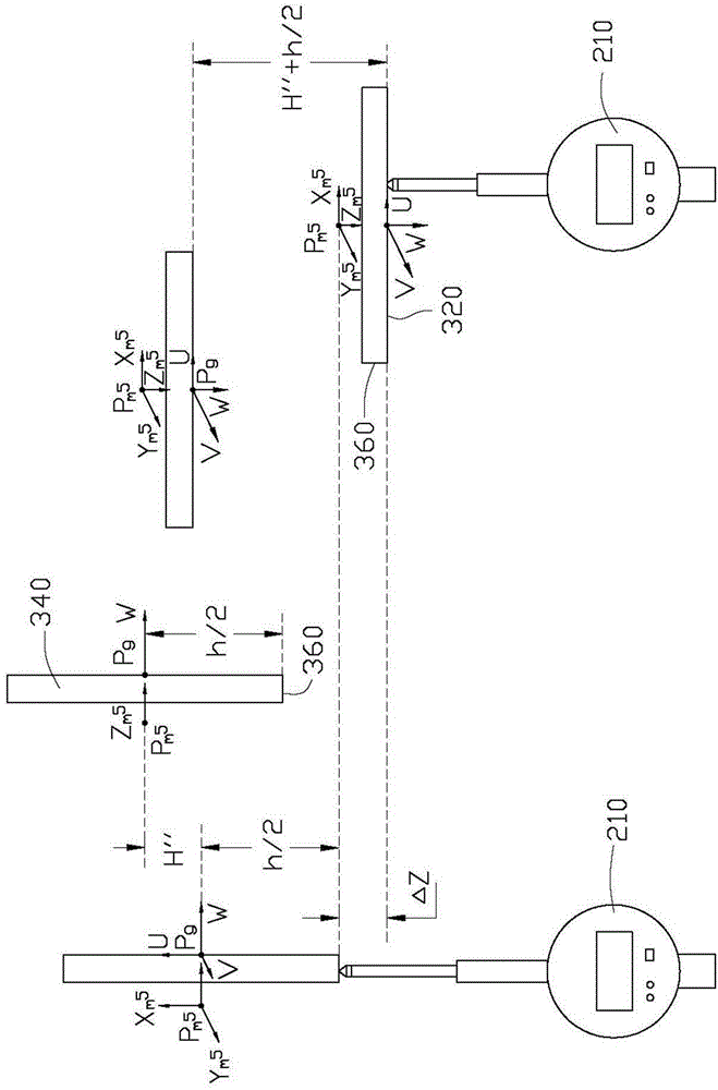
[0015] In practical applications, robots complete various operations by installing actuators (such as processing tools or clamping fixtures) at their ends. In this embodiment, the robot grabs the workpiece through the actuator for processing. Before processing, it is usually necessary to define a tool coordinate system on the workpiece grabbed by the actuator. The accuracy of the tool coordinate system directly affects the precise operation of the robot. In this embodiment, the coordinate system where the workpiece is located is the actual tool coordinate system, and the robot defines a basic tool coordinate system to obtain the actual tool coordinate system of the workpiece grasped by the robot. The correction of the tool coordinate system of the workpiece on the robot by using the robot tool coordinate system correction method of the present invention will be described in detail below.

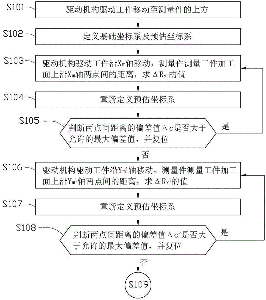
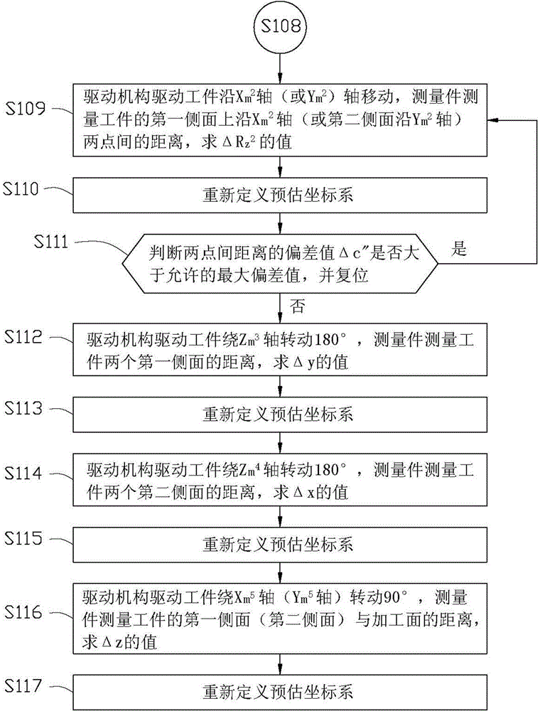
[0016] see Figure 1 to Figure 3 In the robot tool coordinate system calibration method...


PUM


Abstract

A calibration method for a coordinate system of a workpiece held by a robot manipulator, which includes the following steps: setting a predicted coordinate system on the workpiece; controlling the drive mechanism to drive the workpiece to move a specific distance along a coordinate axis in the predicted coordinate system and measuring the distance change of the workpiece in a direction perpendicular to the move; using the measured distance change to determine an orientation error between the predicted coordinate system and the actual coordinate system; correcting the orientation parameters of the predicted coordinate system; controlling the drive mechanism to drive the workpiece to rotate by a specific angle around a coordinate axis of the predicted coordinate system and measuring the distance change after being rotated; using the measured distance change to determine a position error; correcting the position parameters of the predicted coordinate system.

Description

technical field [0001] The invention relates to a method for correcting a robot, in particular to a method for correcting a tool coordinate system of an industrial robot. Background technique [0002] Robotics is widely used in industrial fields, such as automatic assembly, welding, grinding, etc. Various tasks can be accomplished by installing different actuators at the end of the robot, such as pneumatic grippers or processing tools. In the existing robot processing, the processing of the product is generally completed by installing the processing tool at the end of the robot. For example, a grinder is installed on the grinding robot to grind the product fixed on the workbench, and the accuracy of the tool coordinate system of the grinder is established. The accuracy directly affects the grinding accuracy, that is, the accuracy of the robot tool coordinate system becomes an important indicator for the robot to achieve precise operation. However, due to the manual assembl...

Claims


Application Information

Patent Timeline
Patent Type & Authority Applications(China)
IPC IPC(8): G01B21/00
CPCB25J9/16B25J9/1692G05B2219/39021G05B2219/39026Y10S901/02G01B21/00
Inventor 邱隆恩武勇
Owner SHENZHENSHI YUZHAN PRECISION TECH CO LTD
Why Eureka
Try Eureka