Positioning algorithm based on signal gain and loss of 2.5G wireless network
A wireless network signal and positioning algorithm technology, applied in the field of positioning algorithms based on 2.5G wireless network signal gain and loss, can solve the problems of low positioning sensitivity and low positioning accuracy.
- Summary
- Abstract
- Description
- Claims
- Application Information
AI Technical Summary
Problems solved by technology
Method used
Image

Examples
Embodiment Construction
[0042] In order to make the purpose, technical solution and advantages of the present invention clearer, the technical solution of the present invention will be clearly and completely described below in conjunction with specific embodiments of the present invention and corresponding drawings.
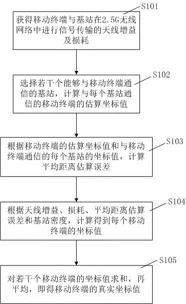
[0043] see figure 1 , figure 1 It is a flow chart S100 of the positioning algorithm based on 2.5G wireless network signal profit and loss of the present invention; the flow chart S100 includes steps S101 to S105;
[0044] In step S101, the antenna gain and loss of the signal transmission between the mobile terminal and the base station in the 2.5G wireless network are obtained; a high-gain directional antenna must be used in the 2.5G wireless network, and the narrower the main lobe width of the antenna, the higher the gain. At a specific power, the higher the gain, the greater the radiation range;
[0045] According to an embodiment of the present application, in the signal transmissi...
PUM
 Abstract
Description
Claims
Application Information
PatSnap Eureka turns technology decisions into work you can execute. Powered by our Innovation Knowledge Graph, it runs expert workflows across engineering, life sciences, materials and intellectual property. Get your review-ready output in minutes.


