Anisotropic conductive adhesive attachment carrier device and anisotropic conductive adhesive attachment method

An anisotropic, conductive adhesive technology, used in nonlinear optics, instruments, optics, etc., can solve the problems of deviation from the Mark position, long time consumption, poor alignment accuracy, etc., to reduce waste of raw materials, save costs, and easily effect of operation

Active Publication Date: 2015-11-25
BOE TECH GRP CO LTD +1
View PDF5 Cites 6 Cited by
  • Summary
  • Abstract
  • Description
  • Claims
  • Application Information

AI Technical Summary

Problems solved by technology

[0002] At present, Rework (heavy industry) FPC (flexible circuit board, flexible circuit board) is to attach anisotropic conductive film (Anisotropic Conductive Film, referred to as ACF) on the FPC on the vacuum stage, and then FPC with ACF and Panel (liquid crystal) Panel) for Bonding (bonding) crimping, the ACF attachment machine used is a semi-automatic machine, manual operation for alignment, and human eyes to align the FPC to the Mark (mark) position, because sometimes the operation speed needs to be accelerated, it is easy to happen Deviating from the Mark position, the alignment accuracy is poor, it is easy to cause alignment deviation, and it takes a long time
If the FPC with ACF and NG is not checked when Bonding FPC (bonding flexible circuit board), and it is pasted on the Panel, it will lead to defective products

Method used


Image

  • Anisotropic conductive adhesive attachment carrier device and anisotropic conductive adhesive attachment method
  • Anisotropic conductive adhesive attachment carrier device and anisotropic conductive adhesive attachment method
  • Anisotropic conductive adhesive attachment carrier device and anisotropic conductive adhesive attachment method

Examples


Embodiment Construction

[0034] The specific embodiments of the present invention will be described in further detail below with reference to the accompanying drawings and embodiments. The following examples are intended to illustrate the present invention, but not to limit the scope of the present invention.

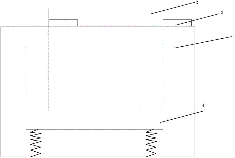
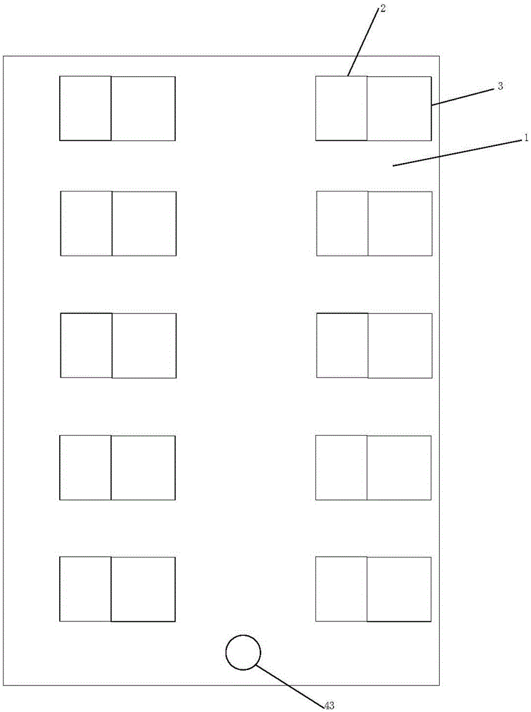
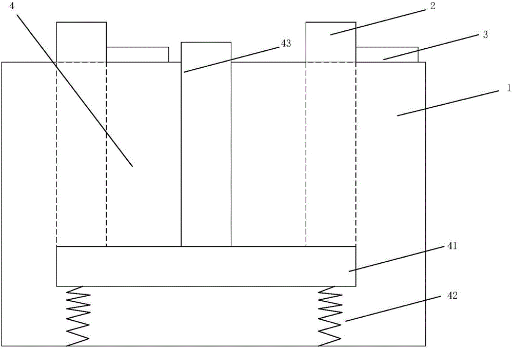
[0035] like Figure 1a-Figure 4 As shown, the present invention provides a device for attaching an anisotropic conductive adhesive to a stage. The device includes: a stage body 1, and a plurality of flexible circuit board areas to be placed on the stage body 1 are arranged on the stage body 1 There is a lifting baffle 2 corresponding to at least one area of ​​the flexible circuit board to be placed; the lifting baffle 2 is aligned with the set edge of the area to be placed on the flexible circuit board; the lifting baffle 2 is on the flexible circuit board 3. Protrudes from the upper surface of the carrier body 1 before alignment; the lift baffle 2 retracts from the upper surface of the carrie...


PUM


Abstract

The invention discloses an anisotropic conductive adhesive attachment carrier device and an anisotropic conductive adhesive attachment method. The device comprises a carrier body. A plurality of areas where flexible circuit boards are to be placed are arranged on the carrier body. At least one lifting baffle corresponding to the areas where flexible circuit boards are to be placed is arranged on the carrier body. The lifting baffles are flush with the set edges of the areas where flexible circuit boards are to be placed. The lifting baffles extend out of the upper surface of the carrier body before the flexible circuit boards are aligned. The lifting baffles retract to the upper surface of the carrier body after the flexible circuit boards are aligned. The lifting baffles are designed on a vacuum adsorption carrier, the FPCs can be directly supported by the lateral sides of the baffles to be aligned without being corrected through human eyes for a long time, the problem of the alignment accuracy of AFC can be effectively solved, and the overall ACF attachment speed can be effectively increased. The anisotropic conductive adhesive attachment carrier device and the anisotropic conductive adhesive attachment method are simple, practical, easy to operate, and capable of reducing raw material waste and saving cost.

Description

technical field [0001] The invention relates to an anisotropic conductive adhesive attaching stage device and an anisotropic conductive adhesive attaching method, belonging to the technical field of liquid crystal manufacturing. Background technique [0002] At present, Rework (heavy industry) FPC (flexible circuit board, flexible circuit board) is to attach anisotropic conductive film (Anisotropic Conductive Film, ACF) to the FPC on the vacuum stage, and then attach the FPC with ACF to Panel (liquid crystal) Panel) for Bonding (bonding) crimping, the ACF attaching machine used is a semi-automatic machine, manual operation is performed for alignment, and the FPC is aligned to the Mark (mark) position with the human eye. Due to the need to speed up the operation sometimes, it is easy to happen. Deviate from the Mark position, the alignment accuracy is poor, it is easy to cause alignment offset, and it takes a long time. If bonding FPC (bonding flexible circuit board) without...

Claims


Application Information

Patent Timeline
Patent Type & Authority Applications(China)
IPC IPC(8): G02F1/13
CPCG02F1/1303
Inventor 黄炯
Owner BOE TECH GRP CO LTD
Why Eureka
Try Eureka