Meta material- microcavity composite structure and preparation method and use thereof

A composite structure and metamaterial technology, applied in the field of nanophotonics, can solve the problems of poor all-optical tunability, long response time, and small nonlinear refractive index of lithium niobate, so as to achieve reduced response time, simple manufacturing process, The effect of enhancing all-optical tunability

Inactive Publication Date: 2015-11-25
PEKING UNIV
View PDF5 Cites 21 Cited by
  • Summary
  • Abstract
  • Description
  • Claims
  • Application Information

AI Technical Summary

Problems solved by technology

The disadvantage of this structure is that the nonlinear refractive index of lithium niobate

Method used


Image

  • Meta material- microcavity composite structure and preparation method and use thereof
  • Meta material- microcavity composite structure and preparation method and use thereof
  • Meta material- microcavity composite structure and preparation method and use thereof

Examples


Embodiment 1

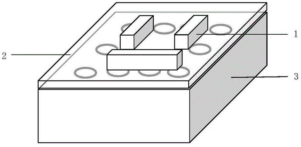
[0038] Such as figure 1 As shown, the metamaterial-microcavity composite structure of this embodiment includes from top to bottom: an upper layer 1, an intermediate layer 2, and a lower layer 3; wherein, the upper layer 1 is a metamaterial; the middle layer 2 is a two-dimensional material; the lower layer 3 is Optical microcavity; the metamaterial on the upper layer has multiple resonant units arranged periodically; the structure of the resonant unit is a broken semi-ring structure, and the material is gold; the two-dimensional material in the middle layer is tungsten disulfide; the optical The microcavity adopts photonic crystal microcavity.

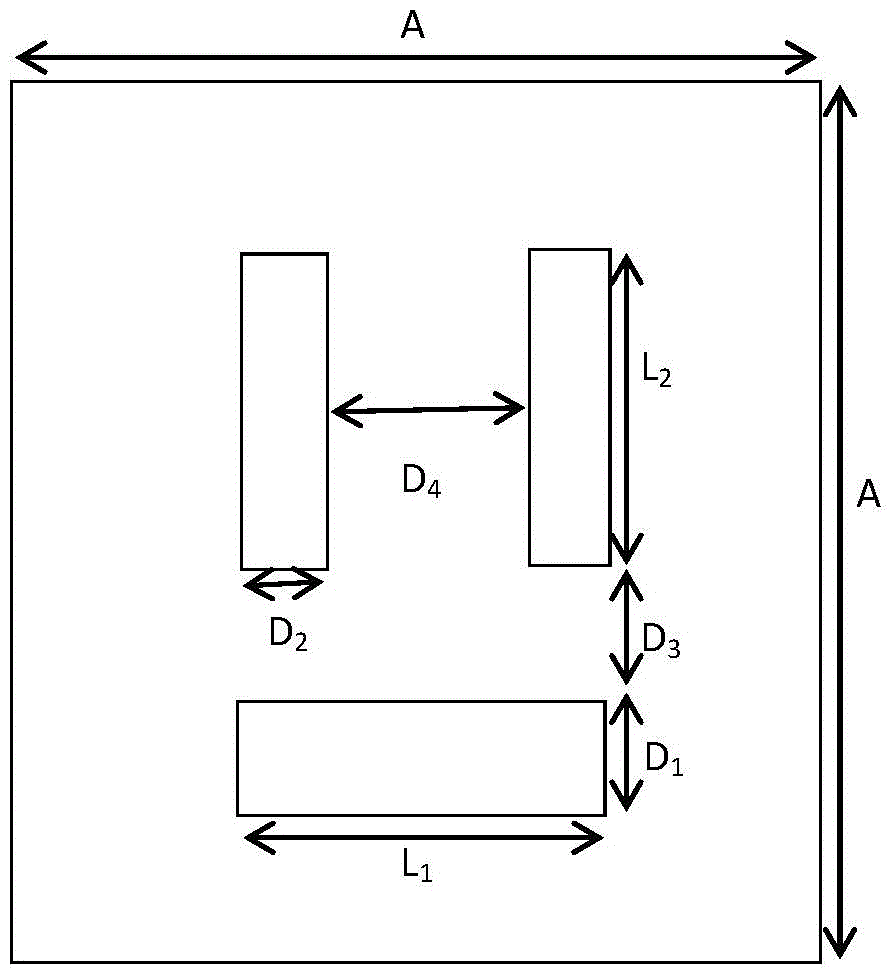
[0039] Such as figure 2 As shown, the broken half-ring structure includes an upper half and a lower half separated from each other; the lower half is a horizontal rectangular metal strip; the upper half is two symmetrical vertical rectangular metal strips. Among them, the period A of the resonance unit is 700nm; the length L of the h...

Embodiment 2

[0044] In this embodiment, the structure of the resonance unit is an asymmetric split-ring structure, such as Figure 6 As shown, it includes an upper half and a lower half separated from each other; the upper half is a ring-shaped metal strip, the lower half is a rectangular metal strip, and the lower half is smaller than the upper half. Among them, the period A of the resonance unit is 765nm; the lower part is a horizontal rectangular metal strip with a length l 1 595nm, width d 1 80nm; the upper part is a half-ring metal strip with a length of l 2 340nm, width d 2 80nm, the inner spacing d of the semi-ring metal strip 4 435nm; the distance d between the upper half and the lower half 3 60nm. Other structures are the same as in Embodiment 1.

[0045] In this embodiment, the metamaterial is an asymmetric split-ring structure arranged periodically, and the probe light is vertically incident on the metamaterial, and the metamaterial is excited by infrared light to generate...

Embodiment 3

[0048] Such as Figure 10 As shown, the metamaterial-microcavity composite structure of this embodiment includes from top to bottom: an upper layer 1, an intermediate layer 2, and a lower layer 3; wherein, the upper layer 1 is a metamaterial; the middle layer 2 is a two-dimensional material; the lower layer 3 is Optical microcavity; the structure of the resonance unit in the upper layer is an asymmetric split-ring structure, including an upper half and a lower half separated from each other; the lower half and the upper half are respectively part circular, and the upper half The radius of the ring is larger than that of the bottom half.

[0049] The structure of the photonic crystal microcavity is as follows Figure 11 As shown, the photonic crystal microcavity in (a) is a point defect formed by removing an air hole in the periodically arranged air holes; the photonic crystal microcavity in (b) is a point formed by reducing the size of an air hole Defect composition; the cry...


PUM

PropertyMeasurementUnit
Thicknessaaaaaaaaaa
Thicknessaaaaaaaaaa
Lattice constantaaaaaaaaaa

Abstract

The invention discloses a meta material-microcavity composite structure and a preparation method and use thereof. The composite structure, from up to down, successively includes: a three-layer composite structure, from up to down, including meta materials, two-dimensional materials and optical microcavities, wherein the upper layer meta materials is provided with a plurality of resonance units arranged periodically. Pump lights incident into the meta materials to cause a change of a nonlinear refractive index of the two-dimensional materials, and a local field enhancement effect of the meta materials stimulated by the pump lights and a local field enhancement effect of the optical microcavities are together to improve the nonlinear refractive index of the two-dimensional materials to allow the effective refractive index around the meta materials to be changed, thereby a transmission state of that lights through composite structure is changed. According to the invention, the nonlinear refractive index of the materials is improved, the response time is reduced, and all-optical adjustability is enhanced. The production process is simple, available materials are wide, and the composite structure of the invention may be used for the all-optical switches or the sensors.

Description

technical field [0001] The invention relates to the field of nanophotonics, in particular to a metamaterial-microcavity composite structure and its preparation method and application. Background technique [0002] Metamaterials refer to some composite materials with artificially designed structures and exhibit extraordinary physical properties that natural materials do not possess. Their properties often do not depend on the intrinsic properties of the constituent materials, but on the artificial structures in them. Metamaterials have potential applications in nanophotonic devices and integrated photonic devices due to their ability to manipulate light at the subwavelength scale. The use of metamaterials to realize all-optical tunable Fano resonances makes it possible to be used in the preparation of nanoscale all-optical switches and sensors. [0003] It has been reported in the literature that a double-layer structure based on metamaterials has achieved all-optical tunabl...

Claims


Application Information

Patent Timeline
IPC IPC(8): G02F1/355
CPCG02F1/3551
Inventor 胡小永周易龚旗煌
Owner PEKING UNIV
Why Eureka
Try Eureka