
Monitoring Method of Scattered Light Parameters of Exposure Machine

A technology of scattered light and exposure machine, which is applied in the field of monitoring scattered light parameters of exposure machines, and can solve the problems of reduced product yield, low efficiency, and long monitoring period

Active Publication Date: 2017-05-24
SEMICON MFG INT (SHANGHAI) CORP
View PDF3 Cites 0 Cited by
  • Summary
  • Abstract
  • Description
  • Claims
  • Application Information

AI Technical Summary

Problems solved by technology

[0007] In view of the shortcomings of the prior art described above, the purpose of the present invention is to provide a method for monitoring the scattered light parameters of the exposure machine, which is used to solve the problem of poor exposure image quality caused by the long monitoring period and low efficiency of the scattered light parameters of the exposure machine in the prior art. , The problem of product yield reduction

Method used


Image

  • Monitoring Method of Scattered Light Parameters of Exposure Machine
  • Monitoring Method of Scattered Light Parameters of Exposure Machine
  • Monitoring Method of Scattered Light Parameters of Exposure Machine

Examples


Embodiment Construction

[0039] Embodiments of the present invention are described below through specific examples, and those skilled in the art can easily understand other advantages and effects of the present invention from the content disclosed in this specification. The present invention can also be implemented or applied through other different specific implementation modes, and various modifications or changes can be made to the details in this specification based on different viewpoints and applications without departing from the spirit of the present invention.

[0040] see Figure 2 to Figure 6 . It should be noted that the diagrams provided in this embodiment are only schematically illustrating the basic idea of ​​the present invention, and only the components related to the present invention are shown in the diagrams rather than the number, shape and shape of the components in actual implementation. Dimensional drawing, the type, quantity and proportion of each component can be changed arb...


PUM

PropertyMeasurementUnit
thicknessaaaaaaaaaa
thicknessaaaaaaaaaa
thicknessaaaaaaaaaa

Abstract

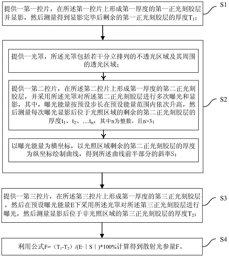
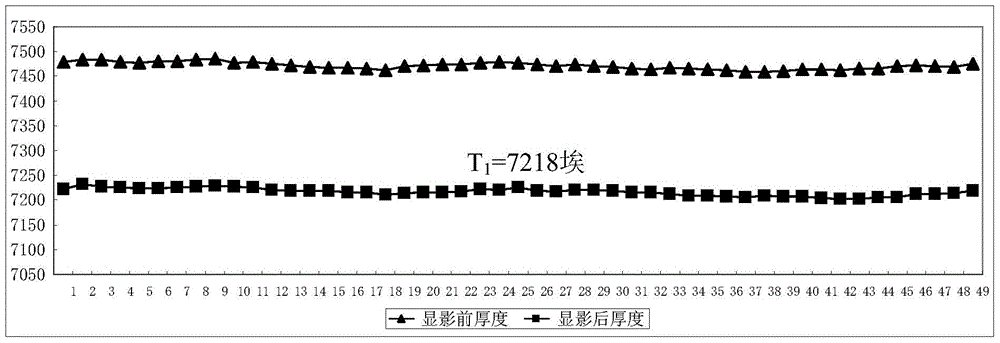
The invention provides a monitoring method for a scattered light parameter of an exposure machine. The monitoring method at least comprises the following steps of S1, providing a first control wafer, forming a first positive photoresist layer on the first control wafer and developing, and measuring to obtain a thickness T1; S2, providing an optical cover and a second control wafer, forming a second positive photoresist layer on the second control wafer, carrying out multiple exposure and developing by using the optical cover, and drawing a curve by taking exposure energy as horizontal coordinates and the thickness of the residual second positive photoresist layer in an illumination region as vertical coordinates to obtain a slope S; S3, providing a third control wafer, forming a third positive photoresist layer on the third control wafer, exposing under predetermined exposure energy E by using the optical cover, and measuring the thickness T2 of the third positive photoresist layer arranged in a non-illumination region after developing; and S4, calculating to obtain the scattered light parameter F according to a formula of F=(T1-T2) / (E*|S|)*100%. By the monitoring method, off-line monitoring on the scattered light parameter F of the exposure machine can be achieved at any time, the period is greatly shortened, thus, the imaging quality of the exposure machine is ensured in real time, and product yield is improved.

Description

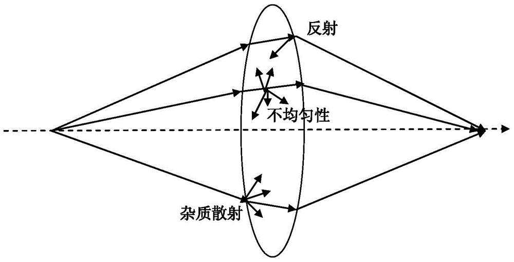
technical field [0001] The invention belongs to the field of semiconductor manufacturing and relates to a monitoring method for scattered light parameters of an exposure machine. Background technique [0002] An exposure machine refers to a device that transfers image information on a film or other transparent body to a surface coated with a photosensitive substance by turning on the light to emit ultraviolet rays of UVA wavelength. In photolithography technology, a photolithography exposure machine generally includes a light source, a mask plate and a lens. A mask is a glass plate whose surface is covered with various patterns, each pattern containing opaque and transparent parts that block and allow light to pass through. The light source can project the pattern onto the wafer coated with photoresist through the mask plate to generate a three-dimensional relief pattern, which is used to assist in etching circuit patterns on the wafer. [0003] The most commonly used expo...

Claims


Application Information

Patent Timeline
Patent Type & Authority Patents(China)
IPC IPC(8): G03F7/20
Inventor 董柏民彭蓉刘桂花
Owner SEMICON MFG INT (SHANGHAI) CORP
Learn More