Eureka AIR delivers breakthrough ideas for toughest innovation challenges, trusted by R&D personnel around the world.

Automatic time collection method for turret clock based on Beidou and GPS double-satellite system

A satellite system and automatic time correction technology, applied in radio-controlled timers, instruments, etc., to solve the problems of inability to know the exact position of the clock hands, troublesome installation, debugging and maintenance, and inability to find and correct pointer position errors.

Inactive Publication Date: 2015-11-25
上海宇丰电子信息科技发展有限公司
View PDF5 Cites 1 Cited by
  • Summary
  • Abstract
  • Description
  • Claims
  • Application Information

AI Technical Summary

Problems solved by technology

The disadvantage of this control method is that the electronic system cannot know the exact position of the clock pointer, and cannot adjust the deviation of the pointer position by itself. Once an error occurs, it must be manually corrected
In order to improve the reliability of use in harsh outdoor environments, some tower clocks use simple mechanical positioning return control and photoelectric code disc control to ensure the relative accuracy of each step of the rotation position, but the existing pointer position errors cannot be found and corrected
The synchronization of the pointer and the digital time can only be realized by using the full digital photoelectric code disc positioning. However, the higher the positioning accuracy requirements are, the more control connections are required. The scale interval of each minute (second) on the 360-degree clock surface is 3 degrees. According to the control requirements of one-third of the scale accuracy, the positioning accuracy is 1 degree, and the binary number of each clock hand 0-359 needs 10 connections. The use of redundant design in harsh environments requires at least 20 wires, which is troublesome for installation, commissioning and maintenance. , it is difficult to promote the use of

Method used


Image

  • Automatic time collection method for turret clock based on Beidou and GPS double-satellite system
  • Automatic time collection method for turret clock based on Beidou and GPS double-satellite system
  • Automatic time collection method for turret clock based on Beidou and GPS double-satellite system

Examples


Embodiment Construction

[0023] In order to make the technical means, creative features, goals and effects achieved by the present invention easy to understand, the present invention will be further described below in conjunction with specific illustrations.

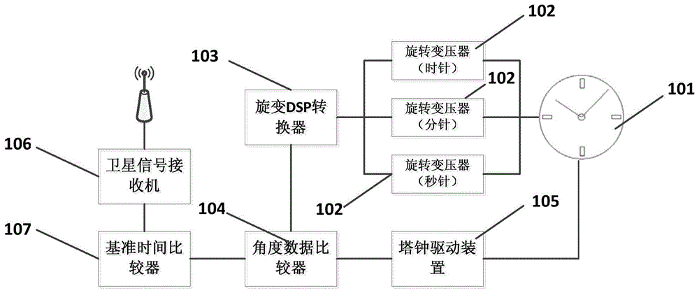
[0024] Such as figure 1 As shown, as an implementation system of the method of the present invention, the system includes a tower clock 101, a rotary transformer 102, a resolver DSP converter 103, an angle data comparator 104, a tower clock driving device 105, a satellite signal receiver 106 and a reference time comparator 107 .

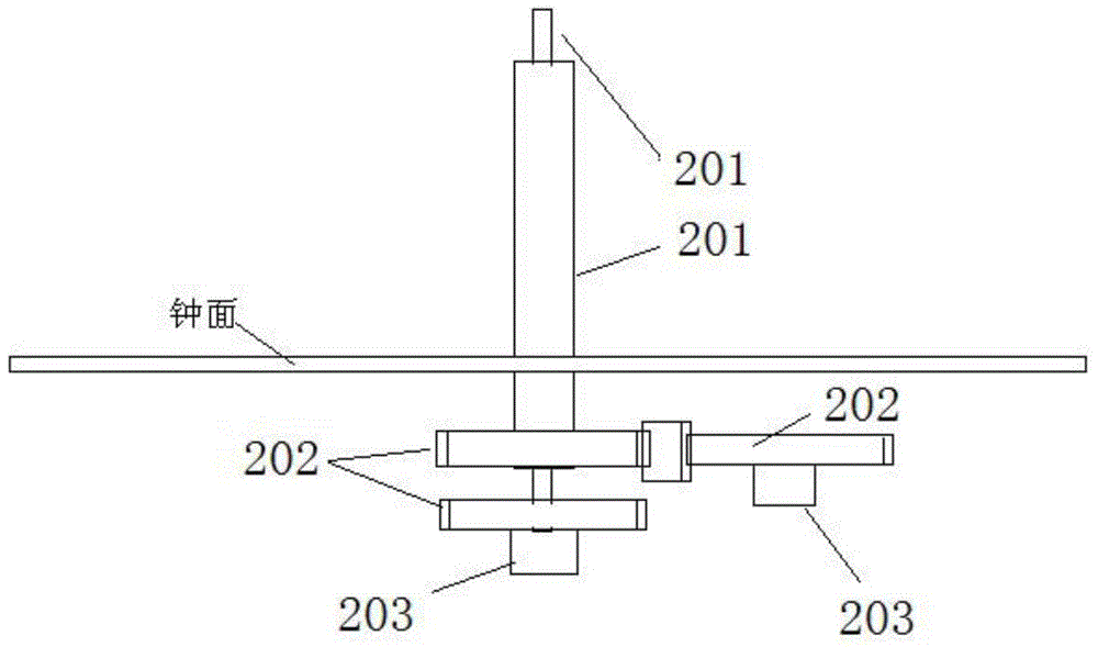
[0025] Wherein, the angle data comparator 104 is respectively connected to the resolver DSP converter 103 , the tower clock driving device 105 and the reference time comparator 107 . The reference time comparator 107 is connected to the satellite signal receiver 106 . The resolver DSP converter 103 is respectively connected with a plurality of resolvers 102 (three resolvers in this example) connected with the hands o...


PUM


Abstract

The invention discloses an automatic time collection method for turret clock based on a Beidou and GPS double-satellite system. The method enables time data to be converted into relative angles of each clock hand relative to the original point (12 o'clock) of a clock face, and breaks through a conventional transmission system where a gear ratio is fixed among a hour hand, a minute hand and a second hand, i.e., a mechanical clock movement which is relatively complex in design and manufacturing. The method employs a mode of closed loop control, and enables each hand to be quickly and accurately positioned at a correct time representation position through a universal part in a gear transmission manner. Therefore, the method irons out the defects of various types of control systems, guarantees the synchronization of a pointer-type turret clock with digital time, does not need a person to be on duty, and can solve a difficulty that a pointer-type clock in a public place is not accurate fundamentally.

Description

Technical field: [0001] The invention relates to the automatic time adjustment of large clocks and watches, in particular to a method for automatically adjusting the time of a tower clock by using the Beidou and GPS dual satellite systems. Background technique: [0002] As we all know, although the high-precision digital timing system is highly developed, the large-scale analog clock is still irreplaceable in both civilian and public occasions. Large tower clocks are mainly used in large public places, such as stations, squares, airports, etc., not only as a timing tool, but also as a symbolic landscape. [0003] However, the current situation is that nine out of ten tower clocks are inaccurate. In order to solve this problem, many domestic methods use manual time adjustment and digital clock time reference signals to control the operation of analog clocks. This method is time-consuming and laborious. Synchronize update time. [0004] At present, the most used is the open-...

Claims


Application Information

Patent Timeline
IPC IPC(8): G04R20/04G04R40/06
Inventor 曾庆文刘世进
Owner 上海宇丰电子信息科技发展有限公司
Why Eureka
Eureka Blog
Learn More