Floating mounting structure of laser electrode plate

An installation structure and electrode plate technology, applied in the field of lasers, can solve the problems of long installation time, weak installation, low installation efficiency, etc.

Active Publication Date: 2015-11-25
JIANGSU ZHUOYUAN LASER TECH
View PDF9 Cites 0 Cited by
  • Summary
  • Abstract
  • Description
  • Claims
  • Application Information

AI Technical Summary

Problems solved by technology

At present, the electrode plate in the laser is generally fixed inside the emitting cavity by screws, welding, etc. The installation structure in this way takes a lo...

Method used


Image

  • Floating mounting structure of laser electrode plate
  • Floating mounting structure of laser electrode plate
  • Floating mounting structure of laser electrode plate

Examples


Embodiment Construction

[0016] The content of the present invention will be further described in detail below in conjunction with the accompanying drawings.

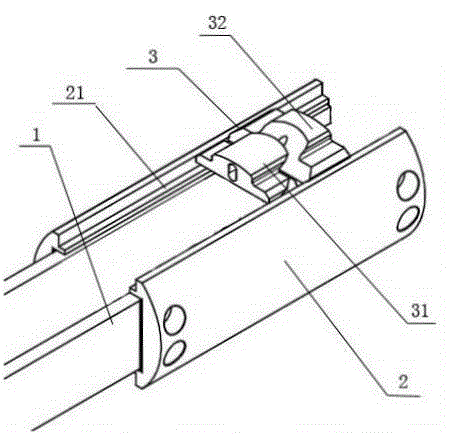
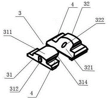
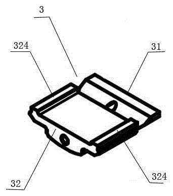
[0017] Such as figure 1 As shown, a floating mounting structure of a laser electrode plate includes an electrode plate 1 and an arc-shaped mounting plate 2 . There are two electrode plates 1, and the two electrode plates 1 are arranged relatively parallel. The arc-shaped mounting plate 2 is installed on the outer side of the electrode plate 1 through an insulating gasket, and the two arc-shaped mounting plates 2 on the outer side of the electrode plate 1 form a hoop structure. The present invention also includes a floating installation assembly 3, which is respectively installed on the upper and lower sides of the arc-shaped installation plate 2, figure 1 The floating installation assembly 3 on the upper side of the arc-shaped installation plate 2 is shown in , the floating installation assembly 3 on the lower side is not marked, and the stru...


PUM

PropertyMeasurementUnit
Heightaaaaaaaaaa

Abstract

The invention discloses a floating mounting structure of a laser electrode plate. The floating mounting structure comprises two electrode plates, arc mounting plates and floating mounting assemblies, wherein the two electrode plates are oppositely arranged in parallel; the arc mounting plates are arranged at the outer sides of the electrode plates through insulating gaskets; the two arc mounting plates on the outer sides of the electrode plates form a hoop structure; the floating mounting assemblies are respectively arranged at the upper sides and the lower sides of the arc mounting plates; each floating mounting assembly comprises a fixed part and a floating part; the fixed parts and the floating parts are provided with matched inclined planes; and the inclined planes of the fixed parts and the floating parts are staggered with one another through drive of bolts. The floating mounting structure is firm, low in manufacturing cost, movable to mount and convenient to overhaul.

Description

technical field [0001] The invention relates to a laser, in particular to a mounting structure of an electrode plate in the laser. Background technique [0002] The gas laser generator uses a certain amount of Co2 gas, oxygen, nitrogen and other inert gases to be mixed in proportion, and then filled into the pre-pumped ultra-high vacuum aluminum alloy laser cavity, and the RF excitation source is fed into the optimized design process. The discharge slab, the Co2 laser mixture gas produces a glow discharge, the discharge process is an energy transfer process, and this process will produce a laser with high beam quality. At present, the electrode plate in the laser is generally fixed inside the emitting cavity by screws, welding, etc. The installation structure in this way takes a long time to install, the installation efficiency is low, the installation is not firm, and the fixed installation structure is not conducive to disassembly and maintenance. Contents of the inventi...

Claims


Application Information

Patent Timeline
IPC IPC(8): H01S3/02
Inventor 万胜文
Owner JIANGSU ZHUOYUAN LASER TECH
Why Eureka
Try Eureka