Method and device for discharging voltage of direct current bus capacitor in power electronic conversion system

A DC bus capacitor, power electronic conversion technology, applied in the direction of output power conversion devices, electrical components, etc., can solve the problems of large occupied space, difficult layout, reduced system efficiency, etc., to achieve the effect of rapid discharge

Active Publication Date: 2015-11-25
维谛新能源有限公司
View PDF6 Cites 13 Cited by
  • Summary
  • Abstract
  • Description
  • Claims
  • Application Information

AI Technical Summary

Problems solved by technology

Obviously, the larger the number of discharge resistors, the faster the capacitor voltage discharge speed; however, the larger the number of discharge resistors, the larger the space occupied, which makes the layout difficult, and also reduces the efficiency of the system during normal operation

Method used


Image

  • Method and device for discharging voltage of direct current bus capacitor in power electronic conversion system
  • Method and device for discharging voltage of direct current bus capacitor in power electronic conversion system
  • Method and device for discharging voltage of direct current bus capacitor in power electronic conversion system

Examples


Embodiment 1

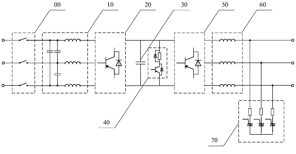
[0034] In Embodiment 1 of the present invention, the three-phase bridge type power electronic conversion system only has a bus chopper circuit, and only uses the bus chopper circuit to discharge the DC bus capacitor voltage.

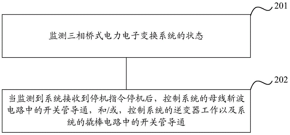
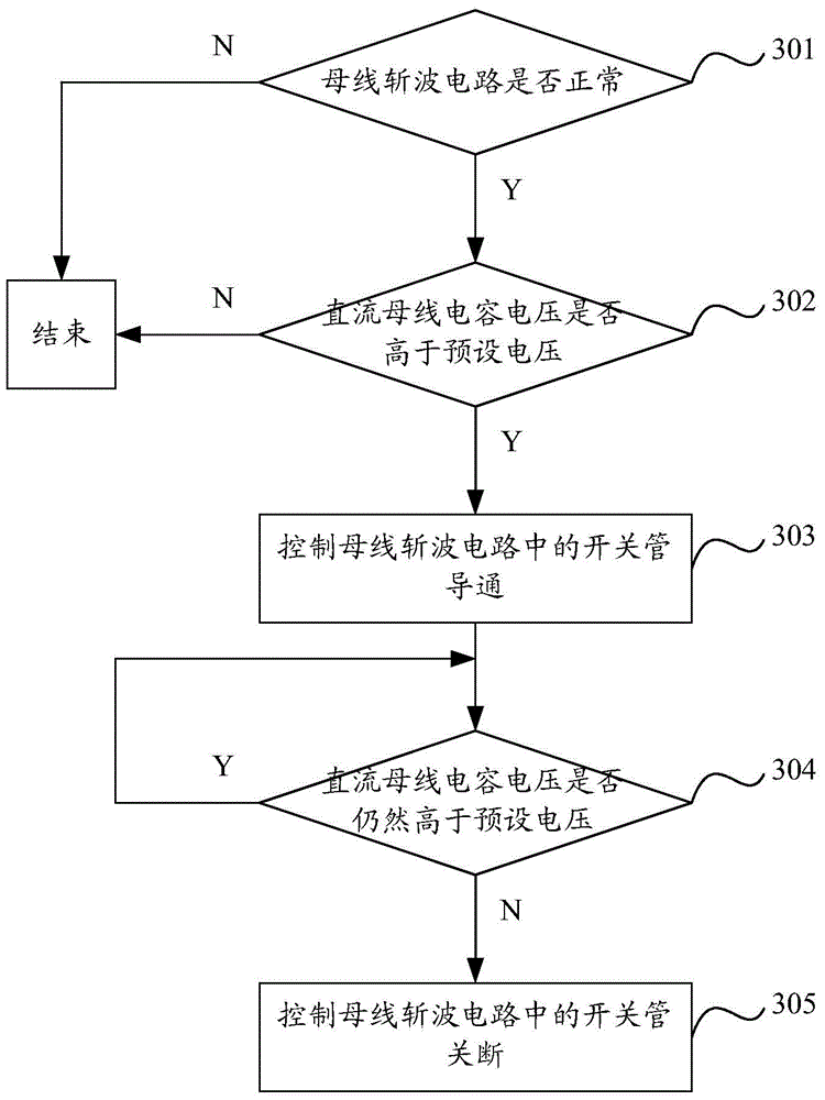
[0035] When the system receives the stop command to stop, execute the following process to realize the discharge of the DC bus capacitor voltage, such as image 3 shown, including:

[0036] Step 301, judging whether the bus chopper circuit of the system is normal.

[0037] When it is determined that the bus chopper circuit of the system is normal, continue to execute the following steps and enter step 302; when it is determined that the bus chopper circuit of the system is abnormal, the process ends.

[0038]In the prior art, there are many methods for judging whether the bus chopper circuit is normal, and any one of the prior art can be used as the specific implementation scheme of this step, and the following method provided by the embodiment of the p...

Embodiment 2

[0059] In Embodiment 2 of the present invention, the three-phase bridge type power electronic conversion system only has a crowbar circuit, and only the crowbar circuit is used to discharge the DC bus capacitor voltage.

[0060] When the system receives the stop command to stop, execute the following process to realize the discharge of the DC bus capacitor voltage, such as Figure 4 shown, including:

[0061] Step 401, judging whether the crowbar circuit of the system is normal.

[0062] When it is determined that the crowbar circuit of the system is normal, continue to perform the following steps, and enter step 402; when it is determined that the crowbar circuit of the system is abnormal, the process ends.

[0063] In the prior art, there are many methods for judging whether the crowbar circuit is normal, and any one of the prior art can be used as the specific implementation scheme of this step, and the following method provided by the embodiment of the present invention c...


PUM


Abstract

The invention discloses a method and a device for discharging the voltage of a direct current bus capacitor in a three-phase bridge type power electronic conversion system, wherein the voltage of the direct current bus capacitor in the three-phase bridge type power electronic conversion system can be discharged based on the hardware of the system itself. In this way, the requirements of safety regulations can be met, while no additionally configured bus discharge resistor in the prior art is adopted. Therefore, the system is higher in operation efficiency, smaller in caloric power and lower in cost.

Description

technical field [0001] The invention relates to the technical field of power electronics, in particular to a method and device for discharging capacitor voltage of a DC bus in a three-phase bridge-type power electronic conversion system. Background technique [0002] In the current three-phase bridge power electronic conversion system, the DC bus capacitor still has a relatively high voltage when the system is shut down. The DC bus capacitor voltage is discharged below the safe voltage within a certain period of time. [0003] figure 1 Shown is a common three-phase bridge power electronic conversion system, including an input switch 00, an input filter 10, a rectifier 20, a DC bus capacitor 30, an inverter 50 and an output filter 60, in order to avoid input short circuit or output When the short circuit causes damage to the rectifier 20 and the inverter 50, a bus chopper circuit 40 and a crowbar circuit 70 are usually provided in the system. The bus chopper circuit 40 inc...

Claims


Application Information

Patent Timeline
Patent Type & Authority Applications(China)
IPC IPC(8): H02M1/00
Inventor 程新伟陈强
Owner 维谛新能源有限公司
Why Eureka
Try Eureka