
Smart T-series light emitting diode (LED) lamp driver and control method therefor

A technology of LED drive and LED lights, applied in energy-saving control technology, lamp circuit layout, lighting devices, etc., can solve the problems that the overall illuminance cannot meet the lighting quality standards, light decay affects LED lighting effects, and LED service life is shortened. To achieve the effect of relatively dispersed and difficult to manage, reasonable circuit design structure, and stable constant current output

Inactive Publication Date: 2015-11-25
王天甜 +3
View PDF6 Cites 5 Cited by
  • Summary
  • Abstract
  • Description
  • Claims
  • Application Information

AI Technical Summary

Problems solved by technology

[0002] At present, there are some problems in the promotion of LED-driven lighting. Due to the excessive LED current, the service life of LED is shortened, and problems such as light decay phenomenon seriously affect the effect of LED lighting.
LED fault monitoring is generally manual inspection without automatic monitoring function. The light decay of LED lighting and the damage of lamps will cause the overall illumination of the environment to fail to meet the lighting quality standard. Therefore, light decay compensation and automatic fault monitoring have become an objective requirement.

Method used


Image

  • Smart T-series light emitting diode (LED) lamp driver and control method therefor
  • Smart T-series light emitting diode (LED) lamp driver and control method therefor
  • Smart T-series light emitting diode (LED) lamp driver and control method therefor

Examples


Embodiment Construction

[0031] In order to express the present invention more clearly, the present invention will be further described below in conjunction with the accompanying drawings.

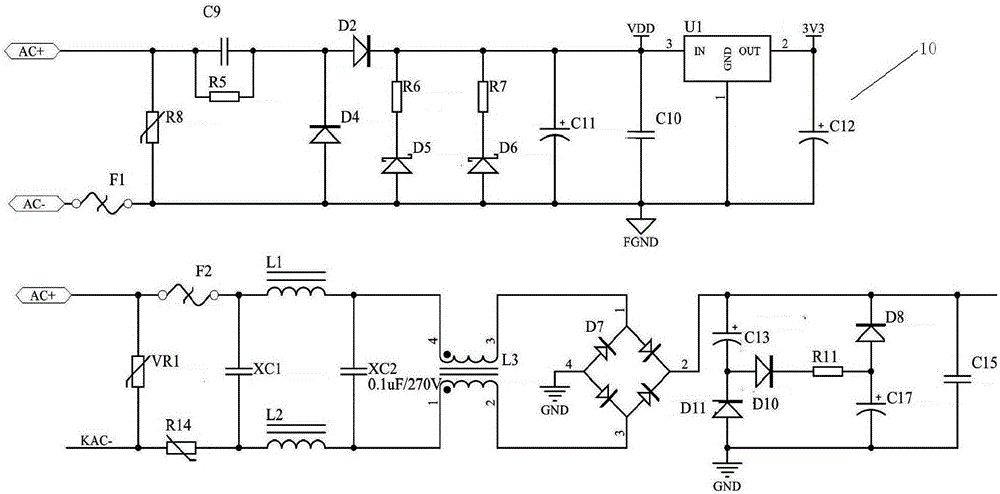
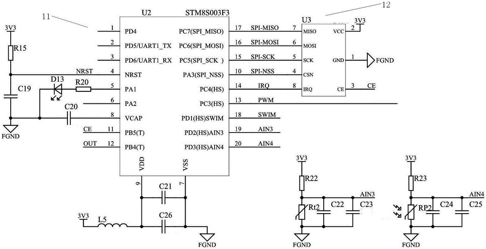
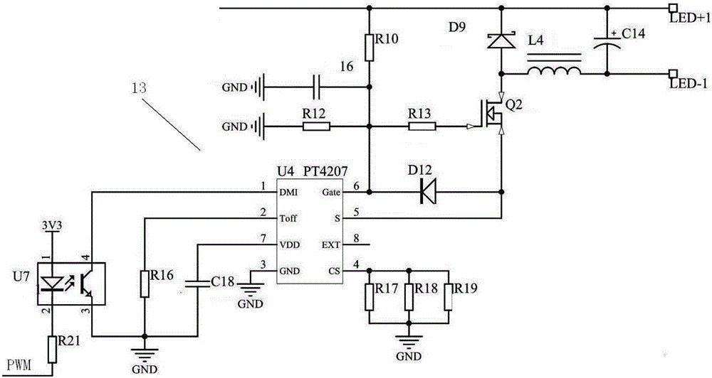
[0032] see Figure 1-3 , the intelligent T series LED lamp driver of the present invention includes a power supply circuit 10 with two power supply channels, a MUC control circuit 11, a communication circuit 12 and an LED drive circuit 13;

[0033] The first path of the power supply circuit 10 is electrically connected to the MUC control circuit 11 and the communication circuit 12 respectively, and the second path of the power supply circuit 10 is electrically connected to the LED drive circuit 13;

[0034]MUC control circuit 11 comprises MUC microprocessor U2, thermistor Rt2 and photoresistor RP2, thermistor Rt2 and photoresistor RP2 are electrically connected with the input end of MUC microprocessor U2 respectively, the output end of MUC microprocessor U2 is connected with The LED drive circuit 13 is electrical...


PUM


Abstract

The invention discloses a smart T-series light emitting diode (LED) lamp driver and a control method therefor. The driver comprises a power supply circuit with two paths of power supply channels, an MUC control circuit, a communication circuit and an LED driving circuit. The first path of the power supply circuit is electrically connected with the MUC control circuit and the communication circuit. The second path of the power supply circuit is electrically connected with the LED driving circuit. The MUC control circuit comprises an MUC microprocessor, a thermistor and a photoresistor. The thermistor and the photoresistor are electrically connected with the input end of the MUC microprocessor. The output end of the MUC microprocessor is electrically connected with the LED driving circuit. The communication end of the MUC microprocessor is in interactive connection with a smart panel of a terminal through the communication circuit. The smart T-series LED lamp driver has the technical characteristics of reasonable circuit design structure, high efficiency and energy conservation, stable constant current output, safe and stable communication, and high reliability.

Description

technical field [0001] The invention relates to the application field of LED lamp driving lighting, in particular to an intelligent T-series LED lamp driver and a control method thereof. Background technique [0002] At present, there are some problems in the promotion of LED-driven lighting. Due to the excessive LED current, the service life of LED is shortened, and problems such as light decay phenomenon seriously affect the effect of LED lighting. LED fault monitoring is generally manual inspection without automatic monitoring function. The light decay of LED lighting and the damage of lamps will cause the overall illumination of the environment to fail to meet the lighting quality standard. Therefore, light decay compensation and automatic fault monitoring have become an objective requirement. [0003] In terms of intelligent lighting systems, scholars at home and abroad have researched and developed relatively independent intelligent lighting systems specially used for ...

Claims


Application Information

Patent Timeline
Patent Type & Authority Applications(China)
IPC IPC(8): H05B37/02
CPCY02B20/40
Inventor 王天甜唐慧王万年唐洪珍
Owner 王天甜
Learn More