Dual clutch transmission

A dual-clutch transmission and clutch technology, which is applied in the direction of machine/engine, gear transmission, transmission control, etc., can solve the problems of large transmission size, high cost, and increased number of parts, so as to prevent cost increase and reduce replacement. The effect of preventing file impact and preventing size enlargement

Active Publication Date: 2013-03-06
HONDA MOTOR CO LTD
View PDF9 Cites 10 Cited by
  • Summary
  • Abstract
  • Description
  • Claims
  • Application Information

AI Technical Summary

Problems solved by technology

[0007] However, in the above-mentioned conventional structure, in order to reduce the shock of shifting, it is necessary to provide a special friction wheel mechanism. Therefore, there is a problem that the number of parts increases corresponding to the friction wheel mechanism, which leads to an increase in cost. An important reason, or the size of the transmission is enlarged

Method used


Image

  • Dual clutch transmission
  • Dual clutch transmission
  • Dual clutch transmission

Examples


no. 1 Embodiment approach

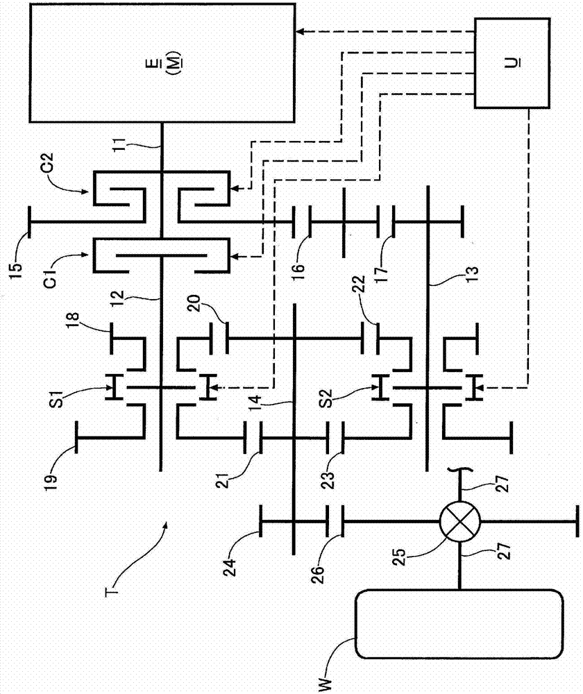
[0031] Such as figure 1 As shown, the dual-clutch transmission T mounted on a vehicle includes: a first input shaft 12 arranged coaxially with a crankshaft 11 of an internal combustion engine E composed of a gasoline engine; a second input shaft 13 parallel to the first input shaft 12 and the output shaft 14 is arranged parallel to the first input shaft 12 and the second input shaft 13 . The driving force of the crankshaft 11 is transmitted to the first input shaft 12 through the first clutch C1, and the driving force of the crankshaft 11 is transmitted to the second input shaft through the second clutch C2, the driving gear 15, the intermediate gear 16, and the driven gear 17. axis 13.

[0032] A first-speed drive gear 18 and a third-speed drive gear 19 are supported on the first input shaft 12 in a relatively rotatable manner. - The 2nd speed driven gear 20 meshes with the 3rd - 4th speed driven gear 21 . In addition, the 2nd speed drive gear 22 and the 4th speed drive ge...


PUM


Abstract

Disclosed is a dual clutch transmission wherein, during a pre-shifting operation wherein, when a vehicle is driven using either a first or a second drive force transmission path extending from first and second input shafts (12, 13) to an output shaft (14), a synchronizer (S1, S2) of the other drive force transmission path is operated, the drive force of an internal combustion engine (E) is changed by a command from an electronic control unit (U), and accordingly, even when a drive force or a braking force is generated by inertia, due to a change in the number of rotations of the first and second input shafts (12, 13) in conjunction with the pre-shifting operation, the drive force or the braking force generated by inertia can be compensated by a change in the drive force of the internal combustion engine (E), to reduce shift-shock. Furthermore, the shift-shock can be reduced by only changing the drive force of the internal combustion engine (E) without adding any special structures to the dual clutch transmission (T), and accordingly, the cost and size of the dual clutch transmission (T) can be prevented from increasing.

Description

technical field [0001] The present invention relates to a dual-clutch transmission that transmits driving force from a driving source to drive wheels via a first driving force transmission path and a second driving force transmission path, wherein the first driving force transmission path passes through a first clutch, a first input shaft, the first gear train, and the output shaft, and the second drive force transmission path passes through the second clutch, the second input shaft, the second gear train, and the output shaft. Background technique [0002] In related dual-clutch transmissions, such a structure is known according to the following patent document 1: a friction wheel mechanism that can be disengaged freely is arranged between the first and second input shafts and output shafts, for example, when downshifting, the The first input shaft or the second input shaft is connected to the output shaft through the friction wheel mechanism, and the rotation speed of the ...

Claims


Application Information

Patent Timeline
Patent Type & Authority Applications(China)
IPC IPC(8): F02D29/00F02D41/04F02P5/15F16H61/04F16H63/50
CPCF02D41/04F16H63/50F16H2306/18F16H61/04F16H2306/42F02P5/15F16H61/0437F02D41/023F16H63/502F02D2250/21F16H61/688F16H3/08F02D29/00Y10T74/19228
Inventor 田伏功藤田威人
Owner HONDA MOTOR CO LTD
Why Eureka
Try Eureka