Method for reducing gradient coil vortex in magnetic resonance imaging system

A technology of magnetic resonance imaging and gradient coils, which is applied in the fields of measuring magnetic variables, medical science, and diagnosis. It can solve the problems of increased magnet manufacturing costs, large DC resistance, and multi-pole space, achieving pole space saving, small drive current, and Avoid Distortion Effects

Inactive Publication Date: 2006-03-08
EAST CHINA NORMAL UNIV
View PDF0 Cites 9 Cited by
  • Summary
  • Abstract
  • Description
  • Claims
  • Application Information

AI Technical Summary

Problems solved by technology

Secondly, since the self-shielding coil is composed of two sets of coils, the main coil and the shielding coil, more pole space is occupied
In order to ensure a certain pole space in actual use, a larger main magnet must be used, resulting in an increase in the cost of magnet manufacturing
Finally, because it consists of two coils instead of the conventional single coil, its DC resistance is relatively large, so the temperature rise of the gradient coil itself is more significant during the imaging process

Method used


Image

  • Method for reducing gradient coil vortex in magnetic resonance imaging system
  • Method for reducing gradient coil vortex in magnetic resonance imaging system
  • Method for reducing gradient coil vortex in magnetic resonance imaging system

Examples


Embodiment

[0025] Below in conjunction with example, feature of the present invention is described in further detail, so that the understanding of those skilled in the art:

[0026] R i

[0027] In the table, R1 to R12 refer to the Figure 4 The radius from the innermost circle to the outermost circle in . Considering that the resistance of the coil should not be too large, the coil generally adopts 8 to 16 turns. The coil is divided into an inner circle and an outer circle. As the coil shrinks, the inner ring will gradually approach the outer ring).

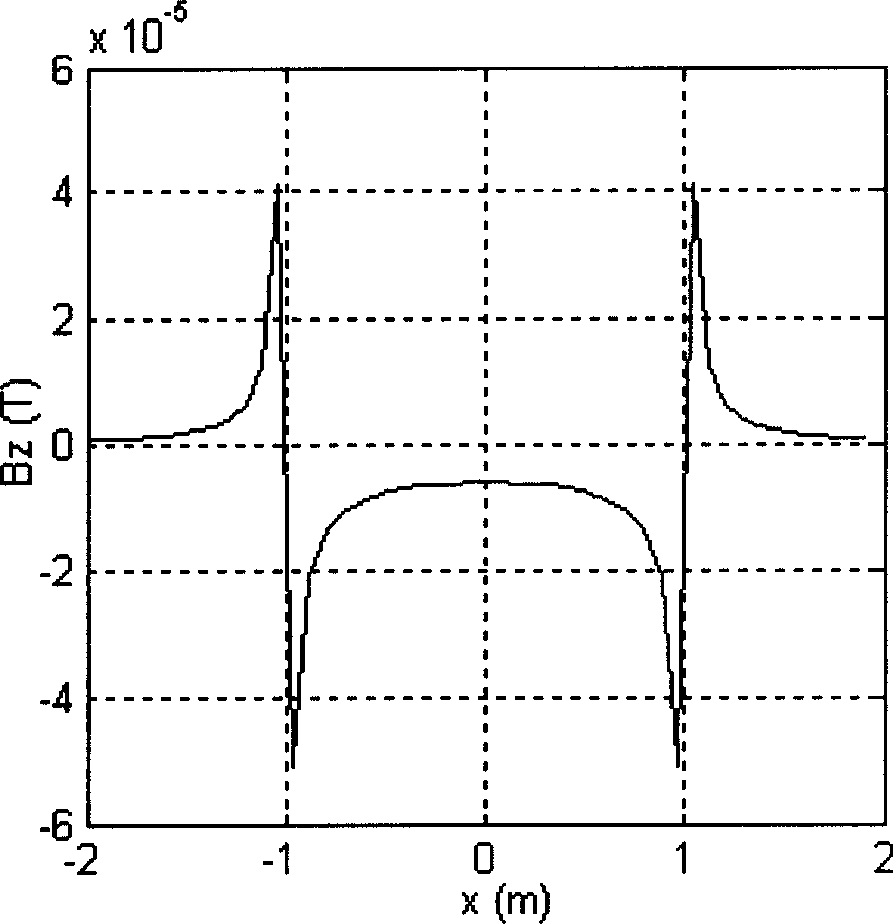
[0028] Raw Z Gradient Coil

[0029] In the experiment, the gradient size of both is 8.5mT / m. It can be seen that the eddy current caused by the Z gradient coil after the radius is reduced is obviously reduced.


PUM


Abstract

The present invention discloses a method for reducing gradient coil eddy current in magnetic resonance image-forming system. Said invention utilizes the method of reducing diameter of Z gradient coil to reduce the eddy current produced by gradient coil and adopts the mode of changing Z gradient coil winding to ensure that the image-forming space is not changed. Said invention also provides the concrete requirements for reducing Z gradient coil diameter, and said method can effectively reduce the eddy current produced by gradient coil.

Description

technical field [0001] The invention relates to a nuclear magnetic resonance imaging (MRI) system, in particular to a method for reducing the eddy current of a gradient coil in the MRI system. Background technique [0002] The current development direction of MRI systems is to increase the imaging speed and obtain images with excellent resolution, signal-to-noise ratio and required feature contrast in the shortest time. In an MRI system, the process of spatially localizing the sample is achieved by applying frequency-encoded and phase-encoded gradient magnetic fields during the imaging sequence. Theoretically, in order to have a good correspondence between the spatial position and the frequency and phase, it is required that the waveform of the gradient magnetic field must be known. However, because there are metal parts in the system, such as: superconducting magnet shell, permanent magnet pole plate, coil and frame, etc. ( figure 1 ). Such components will generate eddy ...

Claims


Application Information

Patent Timeline
Patent Type & Authority Applications(China)
IPC IPC(8): A61B5/055G01R33/341G01R33/385
Inventor 王鹤宁瑞鹏李鲠颖
Owner EAST CHINA NORMAL UNIV
Why Eureka
Try Eureka