Resonant frequency tracking circuit of piezoelectric ceramic transformer

A tracking circuit and piezoelectric ceramic technology, which is applied in the direction of electrical components and automatic power control, can solve the problems of piezoelectric ceramic transformer transmission power and efficiency reduction, natural resonant frequency increase, etc., to reduce drive current and power consumption And temperature rise, the effect of protection is not easy to damage

Active Publication Date: 2013-03-06
CRM ICBG (WUXI) CO LTD
View PDF5 Cites 9 Cited by
  • Summary
  • Abstract
  • Description
  • Claims
  • Application Information

AI Technical Summary

Problems solved by technology

[0005] The object of the present invention is to provide a piezoelectric ceramic transformer resonant frequency tracking circuit, which is used to solve the problem that the inherent resonance frequency of the existing piezoelectric ceramic transformer increases due to the temperature rise during the working process, and further causes the piezoelectric ceramic transformer to The problem of the transmission power and efficiency reduction of the transformer

Method used


Image

  • Resonant frequency tracking circuit of piezoelectric ceramic transformer
  • Resonant frequency tracking circuit of piezoelectric ceramic transformer
  • Resonant frequency tracking circuit of piezoelectric ceramic transformer

Examples


Embodiment Construction

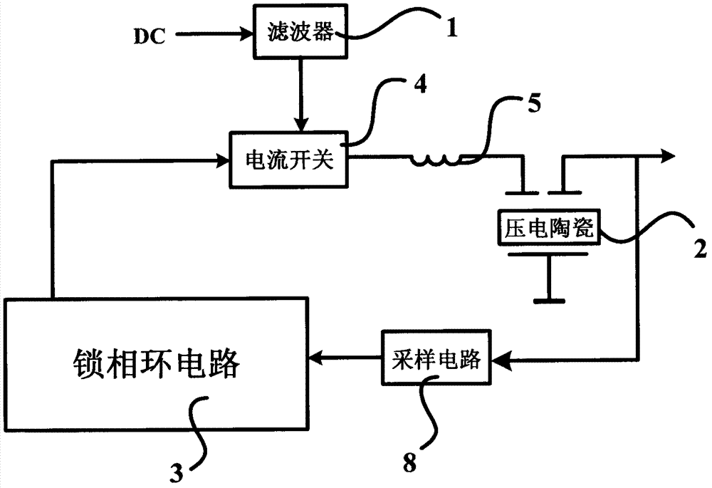
[0031] figure 1 It is a circuit block diagram of an embodiment of the piezoelectric ceramic transformer resonant frequency tracking circuit of the present invention, as figure 1 As shown, in an embodiment of the piezoelectric ceramic transformer resonant frequency tracking circuit, the output voltage of the piezoelectric ceramic is sampled and tracked. The specific circuit structure is: the piezoelectric ceramic 2 is connected to one end of the resonant inductor 5, and a current switch 4 is connected to the other end of the resonant inductance 5, the input end of the current switch 4 is connected to the power supply DC, the input end of a sampling circuit 8 is connected to the output end of the piezoelectric ceramic 2; a phase-locked loop circuit 3 is connected to the sampling circuit 8 The output end is connected, and the other end is connected to the current switch 4. Before the power supply DC is connected to the current switch 4, a filter 1 can also be set for filtering. T...


PUM


Abstract

The invention discloses a resonant frequency tracking circuit of a piezoelectric ceramic transformer. The resonant frequency tracking circuit comprises piezoelectric ceramics, a current switch, a sampling circuit and a phase-locked loop circuit. The piezoelectric ceramics is connected with one end of a resonance inductor, the current switch is connected with the other end of the resonance inductor and is used for converting direct-current voltage input by a power supply into high-frequency pulse current, the sampling circuit is used for sampling input signals or output signals by the piezoelectric ceramics, the phase-locked loop circuit is connected with an output end of the sampling circuit and is used for correcting the sampled signals and outputting the corrected signals as feedback signals to the current switch to control pulse current frequency output by the current switch. The problem that transmission efficiency is lowered since resonant frequency of the piezoelectric ceramic transformer changes along with operation temperature and output load is eliminated and phase of drive frequency can be locked between 105 degrees to 110 degrees by the resonant frequency tracking circuit of the piezoelectric ceramic transformer, and the piezoelectric ceramic transformer is protected from being damaged.

Description

technical field [0001] The invention relates to a piezoelectric ceramic transformer resonant frequency compensation circuit, in particular to a piezoelectric ceramic transformer resonant frequency tracking circuit. Background technique [0002] Piezoelectric ceramic transformers use the piezoelectric effect of piezoelectric ceramics to realize the conversion of electrical energy. Piezoelectric ceramic transformers have the advantages of small size, large transmission power, and high efficiency. Piezoelectric ceramic transformers have the following characteristics: when the temperature rises, the natural resonant frequency rises; when the load increases, the natural resonant frequency rises. The best working state of the piezoelectric ceramic transformer must ensure that the driving frequency is equal to the natural resonance frequency of the piezoelectric ceramic on the one hand, and on the other hand, the phase shift angle must be between 105 and 110 degrees. In order to e...

Claims


Application Information

Patent Timeline
Patent Type & Authority Applications(China)
IPC IPC(8): H03L7/099
Inventor 王新成王立龙陈华吉
Owner CRM ICBG (WUXI) CO LTD
Why Eureka
Try Eureka