Cooling device and cooling method for a rotor-integrated coupling for hybrid modules

A technology for hybrid power modules and cooling equipment, applied in hybrid power vehicles, fluid-driven clutches, mechanically driven clutches, etc., can solve the problems of reducing the quality of clutch operating characteristics or clutch functions, and achieve the effect of saving space

Active Publication Date: 2015-11-25
SCHAEFFLER TECH AG & CO KG
View PDF4 Cites 4 Cited by
  • Summary
  • Abstract
  • Description
  • Claims
  • Application Information

AI Technical Summary

Problems solved by technology

[0003] This rotor-integrated arrangement of the clutch has the disadvantage of reducing the quality of the

Method used


Image

  • Cooling device and cooling method for a rotor-integrated coupling for hybrid modules
  • Cooling device and cooling method for a rotor-integrated coupling for hybrid modules
  • Cooling device and cooling method for a rotor-integrated coupling for hybrid modules

Examples


Embodiment Construction

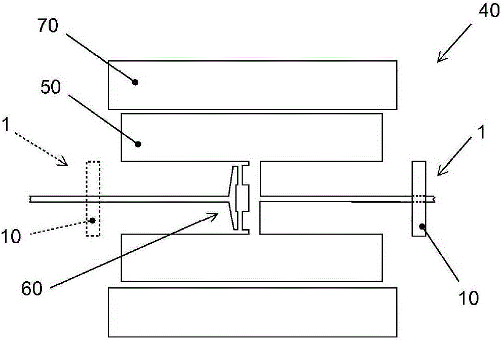
[0027] exist figure 1 , the cooling device 1 has a fluid transport device 10 . The hybrid module 40 has a stator 70 and a rotor 50 in which the clutch 60 is integrated. The fluid transport device 10 is arranged on the rotor 50 on one side of the clutch 60 , for example on the transmission side. The dashed line shows an alternative in which the fluid transport device 10 is arranged on the other side of the clutch 60 , for example on the side of the internal combustion engine. Preferably, the fluid transport device 10 is connected in a rotationally fixed manner to the rotor 50 . In this alternative arrangement (dashed line), the fluid transport device is connected in a rotationally fixed manner to a shaft driven by the internal combustion engine.

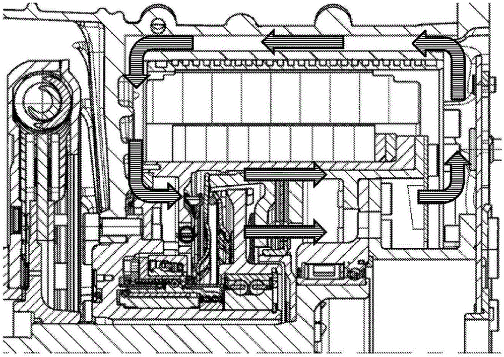
[0028] In operation of the invention, fluid is transported in the direction of the clutch 60 by means of the fluid transport device 10 by suctioning fluid from the area of ​​the clutch 60 so that new, cooler fluid flows from a gre...


PUM


Abstract

The invention relates to a cooling device, wherein the cooling device is a cooling device for a coupling integrated into a rotor of a hybrid module for motor vehicles and the cooling device comprises: at least one fluid transport device which is configured to transport a fluid to the coupling. The invention further relates to a hybrid module for a motor vehicle, wherein the hybrid module comprises a cooling device according to the invention. A hybrid module of this kind shows less wear to the integrated coupling by comparison with others, for example. The invention further relates to a cooling method in which a coupling integrated into a rotor of a hybrid module for a motor vehicle is cooled, wherein the following step is performed: transporting a fluid to the coupling by means of at least one fluid transport device.

Description

technical field [0001] The invention relates to a cooling method and a cooling device for cooling a clutch integrated in a rotor of an electric machine of a hybrid module of a motor vehicle, as well as a hybrid module having such a cooling device. Background technique [0002] A so-called hybrid module of a motor vehicle is shown in DE10036504B4, which contributes to the prior art. It has a clutch which is mounted radially inside the rotor of the electric machine in order to reduce the axial installation space. [0003] The disadvantage of this rotor-integrated arrangement of the clutch is that the quality of the operating characteristics of the clutch or the clutch function is reduced compared to conventionally provided clutches. Contents of the invention [0004] The object of the invention is to improve the prior art with respect to said disadvantages. [0005] The object is achieved by a cooling device, wherein the cooling device is a cooling device for a clutch inte...

Claims


Application Information

Patent Timeline
IPC IPC(8): B60K6/26B60K6/10B60K6/387B60K6/40B60K6/48B60K23/02F16D25/08F16D25/10
CPCB60K6/22B60K2001/006B60K2006/4825F16D13/72F16D2300/0212H02K7/006H02K7/10H02K9/19Y10S903/912Y02T10/62H02K9/06H02K5/20B60K6/38H02K7/108
Inventor 维利·鲁德
Owner SCHAEFFLER TECH AG & CO KG
Why Eureka
Try Eureka