Magnetic field regenerator

A regenerator, magnetic field technology, applied in magnetic resonance accelerators, therapy, radiotherapy, etc., can solve problems such as difficulties

Active Publication Date: 2015-11-25
MEVION MEDICAL EQUIP CO LTD
View PDF18 Cites 2 Cited by
  • Summary
  • Abstract
  • Description
  • Claims
  • Application Information

AI Technical Summary

Problems solved by technology

Implementing the aforementioned field correction using increasingly smaller

Method used


Image

  • Magnetic field regenerator
  • Magnetic field regenerator
  • Magnetic field regenerator

Examples


Embodiment Construction

[0045] Overview

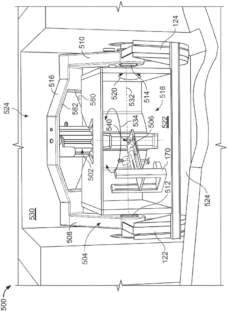
[0046] Described herein are examples of particle accelerators for use in exemplary systems, such as proton or ion therapy systems. The system includes a particle accelerator mounted on a gantry-in this example a synchrocyclotron. As explained in more detail below, the gantry enables the accelerator to rotate around the position of the patient. In some embodiments, the stand is steel and has two legs mounted for rotation on two corresponding bearings located on opposite sides of the patient. The particle accelerator is supported by a steel truss that is long enough to span the treatment area where the patient is located, and is stably attached to the rotating legs of the gantry at both ends. As a result of the gantry rotating around the patient, the particle accelerator also rotates.

[0047] In an exemplary embodiment, the particle accelerator (e.g., a synchrocyclotron) includes a cryostat that houses a superconducting coil for conducting a current that generat...


PUM


Abstract

An example particle accelerator includes the following: a voltage source to provide a radio frequency (RF) voltage to a cavity to accelerate particles from a plasma column, where the cavity has a magnetic field causing particles accelerated from the plasma column to move orbitally within the cavity; an extraction channel to receive the particles accelerated from the plasma column and to output the received particles from the cavity; and a regenerator to provide a magnetic field bump within the cavity to thereby change successive orbits of the particles accelerated from the plasma column so that, eventually, particles output to the extraction channel. The magnetic field is at least 6 Tesla and the magnetic field bump is at most 2 Tesla.

Description

[0001] Cross references to related applications [0002] The priority of U.S. Provisional Application No. 61 / 707,590 filed on September 28, 2012 is hereby claimed, and the content of the U.S. Provisional Application No. 61 / 707,590 is incorporated herein by reference. Technical field [0003] The present disclosure generally relates to a magnetic field regenerator used in a particle accelerator. Background technique [0004] Particle therapy systems use accelerators to generate particle beams for treating diseases such as tumors. In operation, in the presence of a magnetic field, particles accelerate on orbits in the cavity and leave the cavity through an extraction channel. The magnetic field regenerator generates magnetic field bumps near the outside of the cavity to distort the pitch and angle of some tracks so that they move toward the extraction channel and finally enter the extraction channel. Magnetic field regenerators are usually ferromagnetic devices that enhance existing...

Claims


Application Information

Patent Timeline
IPC IPC(8): H05H7/10H05H7/18H05H13/02H05H7/04
CPCH05H13/02A61N5/1077H05H7/04H05H7/10H05H2007/046A61N2005/1087H05H7/02H05H2007/025
Inventor K.P.高尔G.T.兹瓦特J.范德兰C.D.奥尼尔三世K.Y.弗兰岑
Owner MEVION MEDICAL EQUIP CO LTD
Why Eureka
Try Eureka