

Charged-particle beam accelerator, particle beam radiation therapy system, and method of operating the particle beam radiation therapy system
A technology of charged particle beam, medical system, applied in the directions of X-ray/γ-ray/particle irradiation therapy, magnetic resonance accelerator, electrical components, etc., can solve the problems of increasing the amplitude of electron cyclotron vibration, and no RFKO practical frequency control, etc. Achieve the effect of improving reliability, less control objects, and miniaturization of the device
- Summary
- Abstract
- Description
- Claims
- Application Information
AI Technical Summary
Problems solved by technology
Method used
Image

Examples
Embodiment approach 1
[0055] Hereinafter, Embodiment 1 of the present invention will be described with reference to the drawings.
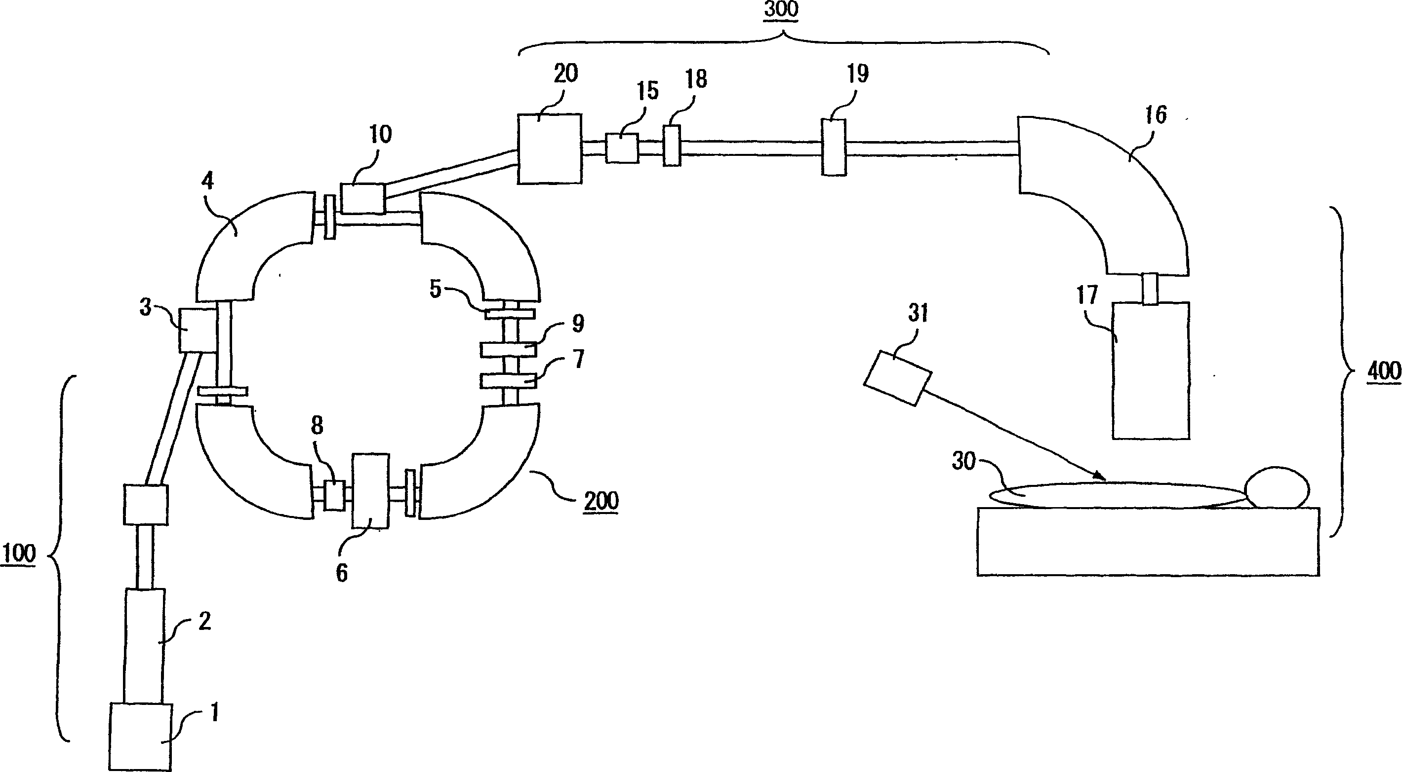
[0056] figure 1It is a diagram showing a particle beam irradiation system in a state where a charged particle beam accelerator and a particle beam irradiation medical system are combined. In the figure, the charged particle beam accelerator 200 is composed of an injection cutting plate (septum) 3, a main deflection electromagnet 4, a main quadrupole electromagnet 5, a high-frequency accelerating device 6, a hexapole electromagnet 7 and a high-frequency generating device. Composed of RFKO equipment 8, injection quadrupole electromagnet 9, and injection cutting plate 10. The charged particle beam accelerator 200 is provided with a low-energy beam injection system 100 at the front end. The injection system consists of an ion source 1 and a linear accelerator 2 . In addition, by using the irradiation device 17 of the irradiation system 400 installed in the medical room,...
Embodiment approach 2
[0076] Next, Embodiment 2 will be described. In the above Embodiment 1, as Image 6 As shown in (d)(f), when operating the injection quadrupole electromagnet 9, it is necessary to disconnect the high-frequency generating device (RFKO equipment) 8, but as Figure 8 As shown in (f), the same effect can be obtained by continuously operating the high-frequency generator 8 which generates the FM modulation signal from frequency f1 to f2. In addition if Figure 9 (f) As shown in (g), if two such high-frequency generators 8 are used as in the conventional example, and a method of shifting the phase of FM modulation is used, more efficient extraction can be performed. further, such as Figure 10 As shown in (f), the same effect can be obtained by using the high-frequency generator 8 that generates signals including frequencies from f1 to f2. Here, the frequency f1 to f2 is a frequency band in which the amplitude of electron cyclotron vibration increases from cyclotron charged part...
Embodiment approach 3
[0083] Next, Embodiment 3 will be described. Because of the interference of the electromagnet power supply of the main deflection electromagnet 4, the main quadrupole electromagnet 5, or the RFKO equipment 8 power supply, etc., in order to make the above-mentioned Image 6 In the period of time other than between the injection start signal (b) and the dose full signal (c), even if there is beam injection, it will not be sent to the spot scanning irradiation device 17, so a more effective way is to The shielding electromagnet 18, which generates a magnetic field between the injection start signal (b) and the dose full signal (c), is set at figure 1 The beam delivery system 300 is shown. The mode of operation of the shielding electromagnet 18 is as Figure 11 (g) shown. In this case, the deflection angle of the deflection electromagnet 20 of the beam delivery system 300 is set to be small, and when the shielding electromagnet 18 is in the off state, the beam deviates from the...
PUM
 Abstract
Description
Claims
Application Information