Backlight and Electronic Equipment

A technology of electronic equipment and backlight, applied in optics, nonlinear optics, instruments, etc., can solve problems such as light leakage in the display area and affect the display performance of electronic equipment, and achieve the effect of avoiding light leakage

Active Publication Date: 2022-03-25
VIVO MOBILE COMM CO LTD
View PDF9 Cites 0 Cited by
  • Summary
  • Abstract
  • Description
  • Claims
  • Application Information

AI Technical Summary

Problems solved by technology

The light projected by the illuminant will be transmitted along the light guide plate of the backlight and reflected at the edge of the light guide plate used to form the opening. Since the edge of the light guide plate forming the opening is relatively small from the display area of ​​the liquid crystal display, therefore More reflected light can be seen in the display area, resulting in visual light leakage in the display area, which will eventually affect the display performance of electronic devices

Method used


Image

  • Backlight and Electronic Equipment
  • Backlight and Electronic Equipment
  • Backlight and Electronic Equipment

Examples


Embodiment Construction

[0022] In order to make the purpose, technical solution and advantages of the present invention clearer, the technical solution of the present invention will be clearly and completely described below in conjunction with specific embodiments of the present invention and corresponding drawings. Apparently, the described embodiments are only some of the embodiments of the present invention, but not all of them. Based on the embodiments of the present invention, all other embodiments obtained by persons of ordinary skill in the art without making creative efforts belong to the protection scope of the present invention.

[0023] The technical solutions disclosed by various embodiments of the present invention will be described in detail below in conjunction with the accompanying drawings.

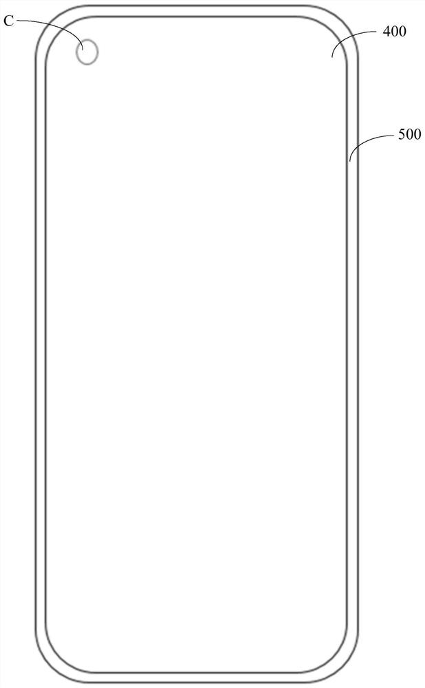
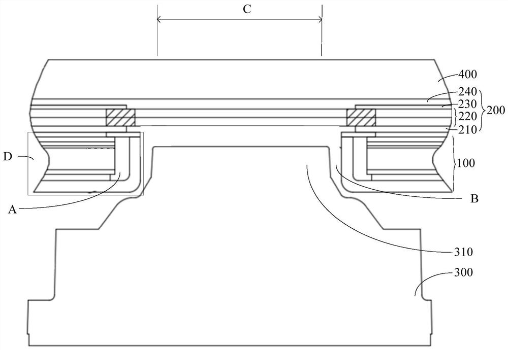
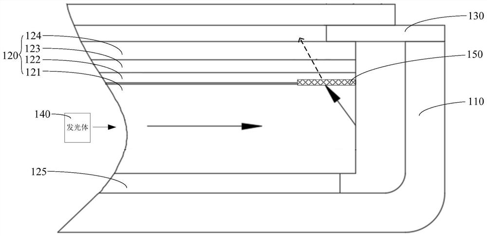
[0024] The embodiment of the present invention discloses a backlight source 100. The disclosed backlight source 100 is applied to electronic equipment. The electronic equipment includes a displa...


PUM


Abstract

The invention discloses a backlight source, comprising a luminous body (140), a support frame (110) and an optical assembly (120), the luminous body (140) is arranged on one side of the optical assembly (120), and the optical assembly (120) includes The light guide plate (121), diffusion sheet (122) and brightness enhancement film are stacked in the support frame (110), the illuminant (140) is arranged on the side of the light guide plate (121), and the optical component (120) has a The avoidance hole (A) in the thickness direction, the part of the support frame (110) located in the avoidance hole (A) encloses the shooting hole (B), and the diffusion sheet (122) surrounds the avoidance hole (A) and faces away from the illuminant (140 ) and the part of the light guide plate (121) that surrounds the avoidance hole (A) and faces away from the illuminant (140) is provided with a light-blocking strip (150). The above solution can solve the problem of light leakage in the backlight openings of the current electronic equipment. The invention discloses an electronic device.

Description

technical field [0001] The invention relates to the technical field of communication equipment, in particular to a backlight source and electronic equipment. Background technique [0002] With the improvement of user needs, the performance of electronic equipment is becoming more and more optimized. At present, electronic devices are developing towards a larger and larger screen-to-body ratio. How to increase the screen-to-body ratio of electronic devices is the current focus of research and development by electronic device manufacturers. [0003] However, the front camera of the electronic device is usually arranged on one side of the display screen, which will occupy a larger board space of the electronic device, and eventually affect the screen ratio of the electronic device. Based on this, the hole-digging screen has become an effective solution commonly used in current electronic equipment. Under the premise of not affecting the normal shooting of the camera set under...

Claims


Application Information

Patent Timeline
Patent Type & Authority Patents(China)
IPC IPC(8): G02F1/13357G02F1/1335
CPCG02F1/133615G02F1/133606G02F1/133512
Inventor 徐飙刘风
Owner VIVO MOBILE COMM CO LTD
Why Eureka
Try Eureka