
Irradiation System and Irradiation Method

a technology which is applied in the field of irradiation system and irradiation method, can solve the problems of continuous intensity loss, and achieve the effects of increasing the safety of the system, reducing the risk of isolated data corruption, and rapid and efficient plausibility check

Inactive Publication Date: 2010-05-13
VERW
View PDF9 Cites 22 Cited by
  • Summary
  • Abstract
  • Description
  • Claims
  • Application Information

AI Technical Summary

Benefits of technology

[0010]For this reason, systems for irradiating patients with charged particles comprise a plurality of safety devices for checking the therapeutic planning data and the functionality of the system, so that incorrectly calculated therapy planning data and data transmission errors between the individual components of the system can be minimized. Thus even isolated data corruption (random errors), which can also have highly disadvantageous effects on the results of the irradiation treatment, can be excluded even more effectively.
[0011]It is an object of the present invention to provide a system for irradiating patients with charged particles which creates an additional and even more efficient redundancy with respect to safety measures, namely, a redundancy which makes it possible for the clinical user to obtain transparent access to the monitored data and by means of which, in addition, the risk of isolated corruption of the data on which the treatment is based can be minimized immediately prior to the irradiation, and to provide a corresponding method for monitoring the system for irradiating patients with charged particles.
[0012]According to an aspect of the invention, the system for irradiating patients with charged particles comprises a raster scanning irradiation unit, which comprises a particle accelerator, a beam guide unit, and a 3D scanning system, wherein the 3D scanning system comprises an energy variation unit for setting the energy of the particle beam and thus the penetration depth of the beam into the patient in the beam direction and a deflecting unit with several deflecting magnets for the two-dimensional deflection of the beam between individual raster points in each layer of predefined penetration depth in the patient—layers which are defined by the energy variation unit and which are situated transversely to the beam direction. In addition, the system comprises a therapy planning system for generating therapy planning data, which comprise the energy and number of charged particles for each raster point in each layer as derived from the desired dose distribution, and a therapy control system, which converts the therapy planning data generated by the therapy planning system into irradiation data and irradiation commands for the particle accelerator, the beam guide unit, and the 3D scanning system. Finally, the system comprises a plurality of safety devices for ensuring that the therapy planning data have been converted correctly and for verifying the functionality of the system, these devices comprising an evaluation unit, which checks the irradiation data and the irradiation commands supplied by the therapy control system to the 3D scanning system to verify their therapy-specific plausibility.
[0013]As a result, an additional safety component is instrumentalized, which can recognize isolated data corruption in the irradiation data and irradiation commands immediately prior to the irradiation and thus increase the safety of the system even more. In particular, the clinically determined relationships are used to conduct a rapid and efficient plausibility check and thus to increase the safety of the treatment.
[0014]The corresponding method for monitoring a system for irradiating patients with charged particles comprises the following steps:
[0015]providing a raster-scanning irradiation unit, which comprises a particle accelerator, a beam guide unit, and a 3D scanning system, wherein the 3D scanning system comprises an energy variation unit for setting the energy of the particle beam and thus the penetration depth of the beam into the patient in the beam direction, and a deflecting unit with several deflecting magnets for the two-dimensional deflection of the beam between individual raster points in each of the layers of predetermined penetration depth in the patient, which layers are defined by the energy variation unit and are oriented transversely to the beam direction;

Problems solved by technology

Conventional photon beams penetrate the body, but they are also absorbed during their interaction with the molecules of the body and thus undergo a continuous loss of intensity.

Method used


Image

  • Irradiation System and Irradiation Method
  • Irradiation System and Irradiation Method
  • Irradiation System and Irradiation Method

Examples


Embodiment Construction

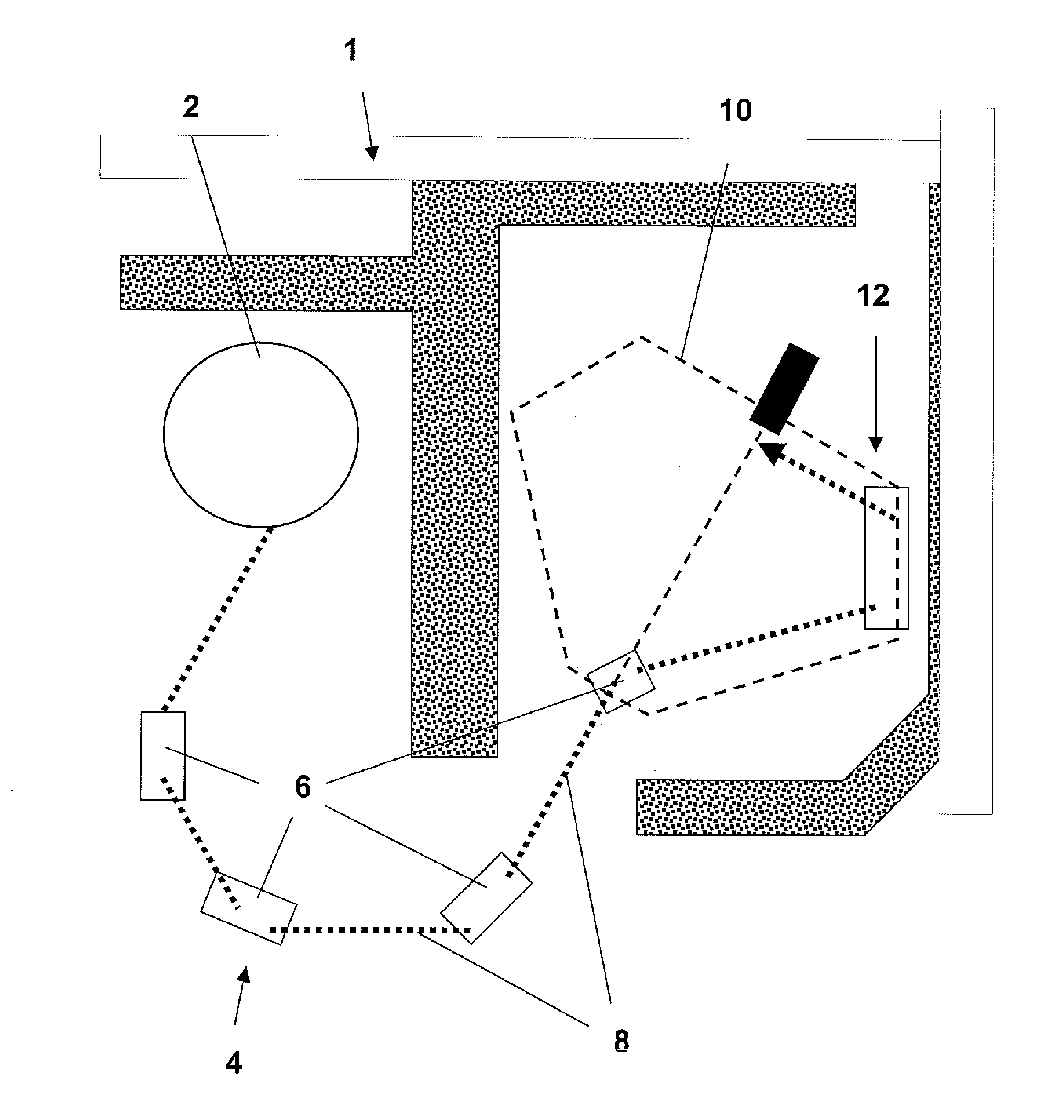
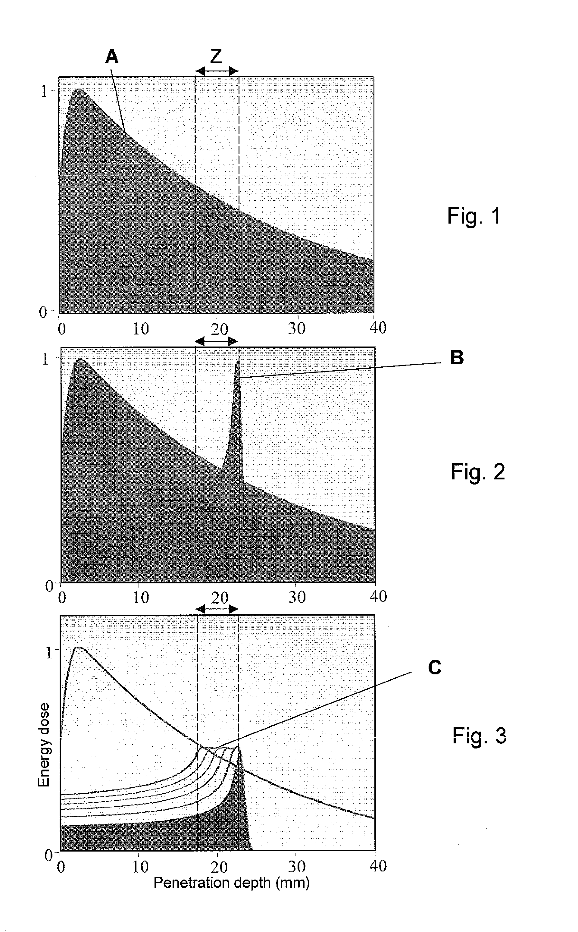
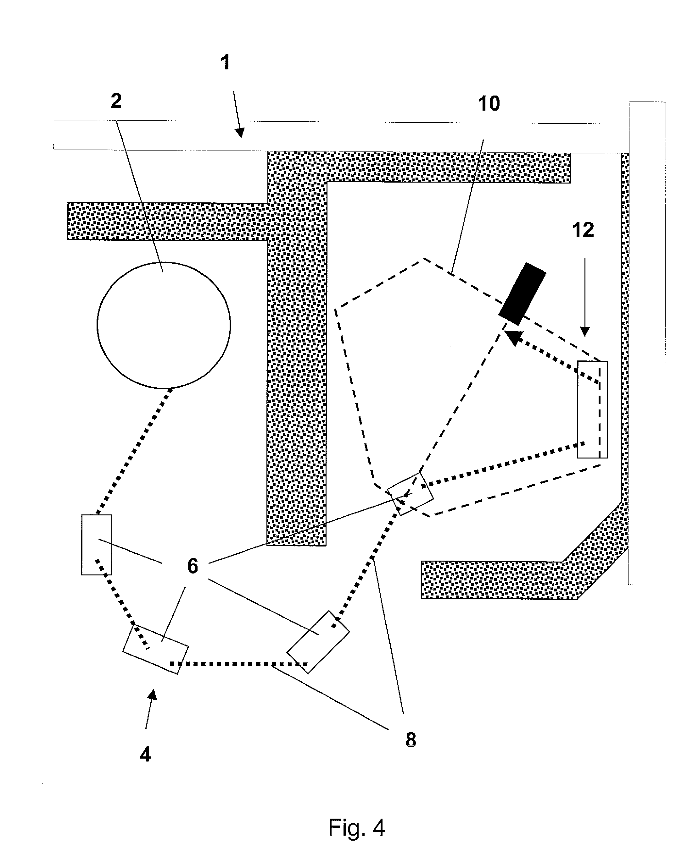
[0043]To achieve the uniform irradiation profile of tumor tissue in the human body shown in FIG. 3 or a profile which can be adapted as desired, the system for irradiating patients with charged particles according to the invention comprises a raster scanning irradiation unit 1, which is illustrated schematically in FIG. 4. The raster scanning irradiation unit 1 comprises a particle accelerator 2 for charged particles. Protons or heavy ions, for example, can be used as the charged particles for the irradiation of tumors. The raster scanning irradiation unit 1 also comprises a beam guide unit 4, which consists of several beam guide magnets 6 and usually straight beam guide sections 8 arranged between the magnets. One of the most important requirements when irradiating patients with charged particles is that the beam be guided with extreme precision. The particle beam is conducted by the beam guide unit 4 into a treatment room, in which, in the present example, a gantry 10 is arranged,...


PUM


Abstract

The system for irradiating patients with charged particles includes a raster scanning irradiation unit with a particle accelerator, a beam guide unit, and a 3D scanning system. It also contains a therapy planning system for generating therapy planning data, which include the energy and number of charged particles per raster point in each layer as derived from the derived dose distribution; a therapy control system, which converts the planning data generated by the therapy planning system into irradiation data and irradiation commands for the particle accelerator, the beam guide unit, and the 3D scanning system. The system further has a plurality of safety devices for ensuring that the therapy planning data have been converted correctly and for verifying the functionality of the system. The plurality of safety devices includes an evaluation unit, which checks the irradiation data and irradiation commands supplied by the therapy control system to the 3D scanning system to verify their therapy-specific plausibility.

Description

BACKGROUND OF THE INVENTION[0001]1. Field of the Invention[0002]The present invention pertains to a system for irradiating patients with charged particles and to a method for monitoring the system.[0003]2. Description of the Related Art[0004]Irradiation systems that irradiate using charged particles offer considerable advantages over conventional irradiation systems which work with x-rays or photon beams. These advantages include the greater accuracy with which the administered dose can be targeted and the decrease in the severity of the side effects on healthy tissue.[0005]Conventional photon beams penetrate the body, but they are also absorbed during their interaction with the molecules of the body and thus undergo a continuous loss of intensity. The maximum dose is present just under the skin, as can be seen from dose-distribution curve A in FIG. 1. This effect is based on the “recruiting” of stray radiation, which occurs after the beam has reached a point just under the skin. As...

Claims


Application Information

Patent Timeline
IPC IPC(8): A61N5/00
CPCA61N5/103A61N5/1043A61N2005/1087
Inventor RINECKER, HANSHAUFFE, JOERG
Owner VERW
Learn More