

Charged particle accelerator
a particle accelerator and charge technology, applied in the direction of accelerators, direct voltage accelerators, electric discharge tubes, etc., can solve the problem of adverse magnetic field affecting the orbit of accelerated particles, and achieve the effect of high reliability
- Summary
- Abstract
- Description
- Claims
- Application Information
AI Technical Summary
Benefits of technology
Problems solved by technology
Method used
Image

Examples
first embodiment
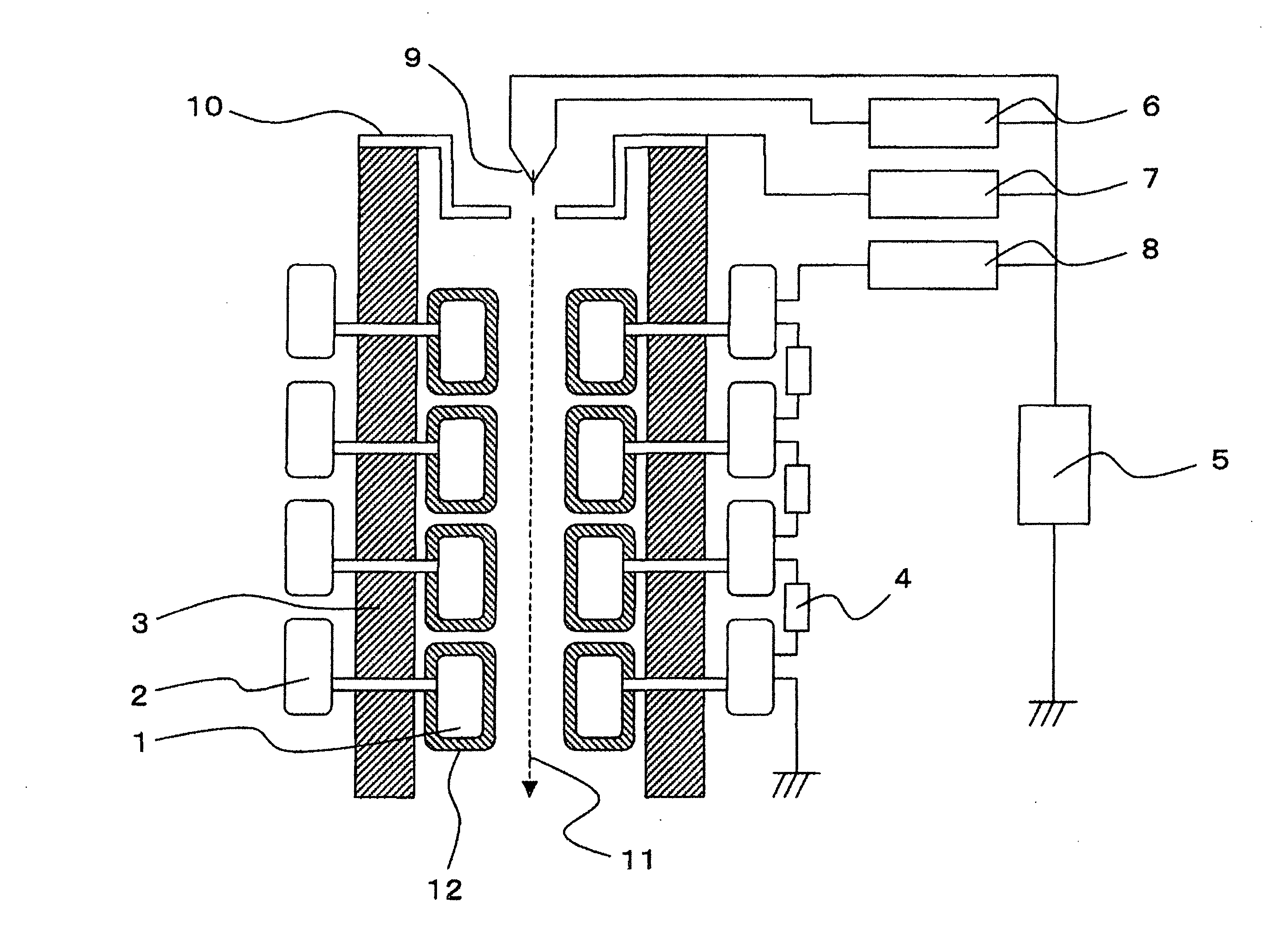
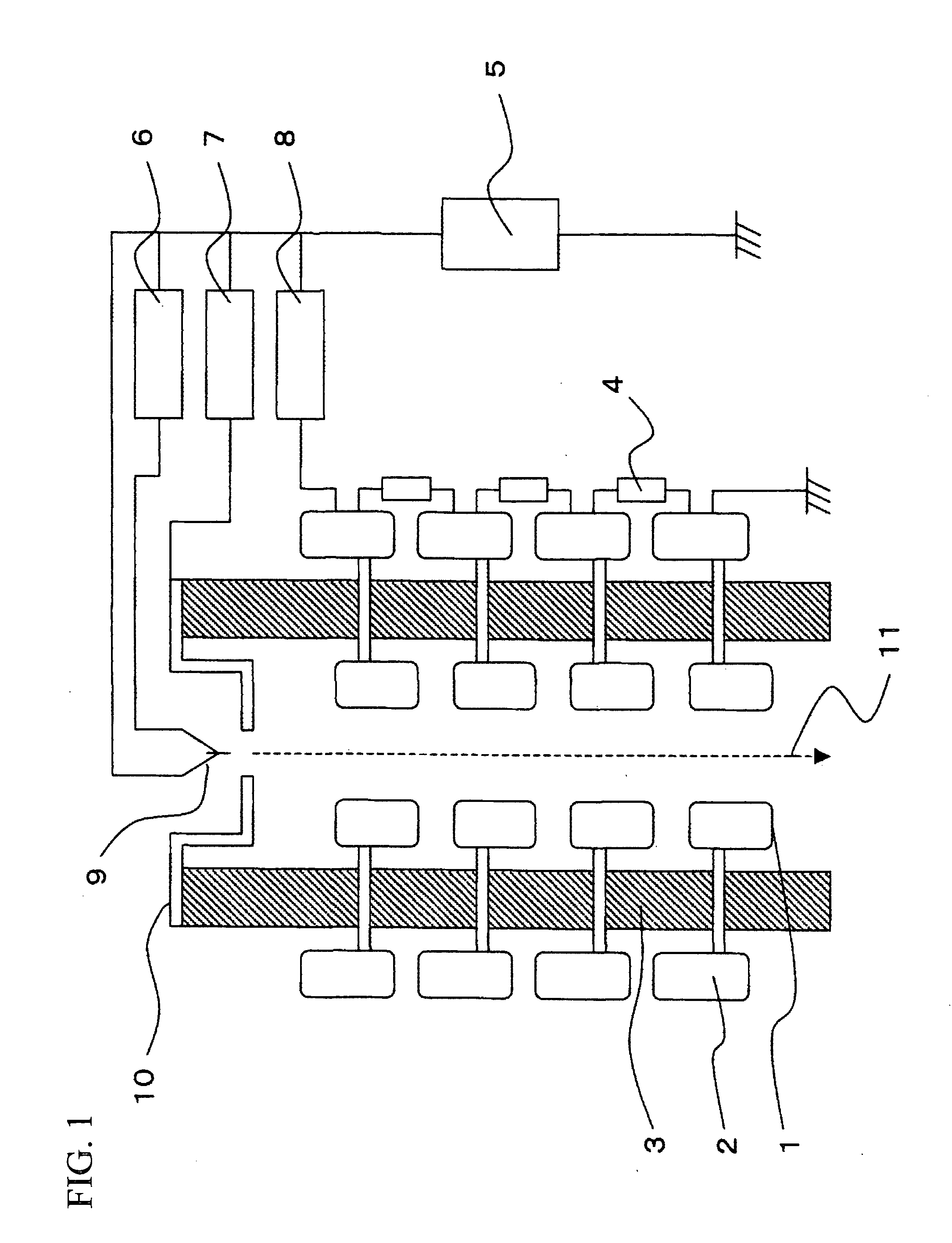
[0024]The first embodiment explains an example of an accelerating tube in which electrodes are coated with ceramics containing alumina by use of FIG. 3. In this embodiment, a structure is provided in which the entire surrounding of each of the inner electrodes 1 is coated with ceramics 12 containing Al2O3 of 80 wt % or more. As the electrode, metal such as iron, stainless, copper, aluminum is exemplified. Thus, part or entirety of the electrode is enclosed with the ceramics 12 having a high melting point as compared with the metal, whereby vapor is hardly generated from the electrode when a clump collides with the electrode, thus allowing electric discharge to be suppressed. Moreover, in this embodiment, although the structure is provided in which the entire surrounding of the inner electrode 1 is coated with a ceramics layer containing alumina, a structure may be possible in which the part thereof is coated therewith. In this case, it is desirable that a ceramics layer should be fo...
second embodiment
[0025]A second embodiment explains an example of an accelerating tube in which each electrode is coated with alumina containing titania (TiO2) as a ceramics layer, similar to the first embodiment. The structure of the accelerating tube of this embodiment is substantially the same as that illustrated in FIG. 3, and alumina containing TiO2 of 1 wt % or more and 20 wt % or less is used as the layer of ceramics 12.
[0026]Thus, mixture of TiO2 into the ceramics 12, which encloses the electrode, allows resistivity of the ceramics 12 to be reduced. Moreover, mixture of titania into the alumina allows resistivity of the alumina to be reduced to about 1 / 100 at the maximum. When a clump adheres to the surface of the ceramics, the reduction in resistivity of the ceramics 12 makes it possible to decrease an electric field of its surrounding. This also reduces the electrostatic force which accelerates the clump that causes electric discharge, thus suppressing electric discharge due to separation ...
third embodiment
[0028]The third embodiment explains an example of an accelerating tube in which each electrode is coated with alumina containing TiC as a ceramics layer, similar to the first embodiment. The structure of the accelerating tube of this embodiment is substantially the same as that illustrated in FIG. 3, and alumina containing TiC of 1 wt % or more and 20 wt % or less is used as the layer of ceramics 12.
[0029]Mixture of TiC into the ceramics 12 allows resistivity of the ceramics 12 to be reduced. When a clump is adhered to the surface of the ceramics, the reduction in resistivity of the ceramics 12 makes it possible to decrease an electric field of its surrounding. This reduces electrostatic force which accelerates the clump that causes electric discharge, thereby suppressing electric discharge due to separation of the clump. Particularly, it is preferable that the electrical resistivity of the ceramics 12 should be set to 108Ω*cm or more and 1015Ω*cm or less. Even in a case of ceramics...
PUM
 Abstract
Description
Claims
Application Information