

Lumen flusher
A flusher and lumen technology, which is applied in the field of medical devices, can solve the problems of unclearness, lens pollution, and inconvenient flow control of syringes, etc., and achieve the effect of stable liquid flow and clear surgical field of view
- Summary
- Abstract
- Description
- Claims
- Application Information
AI Technical Summary
Problems solved by technology
Method used
Image

Examples
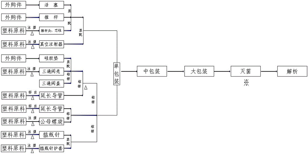
Embodiment 1
[0034] The liquid outlet unit is a bypass line 4 , and the bypass line 4 is a hose connecting the liquid inlet joint and the liquid outlet 3 .
Embodiment 2
[0036] The liquid outlet unit includes,
[0037] Two-way check valve 2, which is a three-way pipe structure, one end of the two-way check valve 2 is connected to a liquid inlet pipe, and the port of the liquid inlet pipe is provided with the liquid inlet joint;
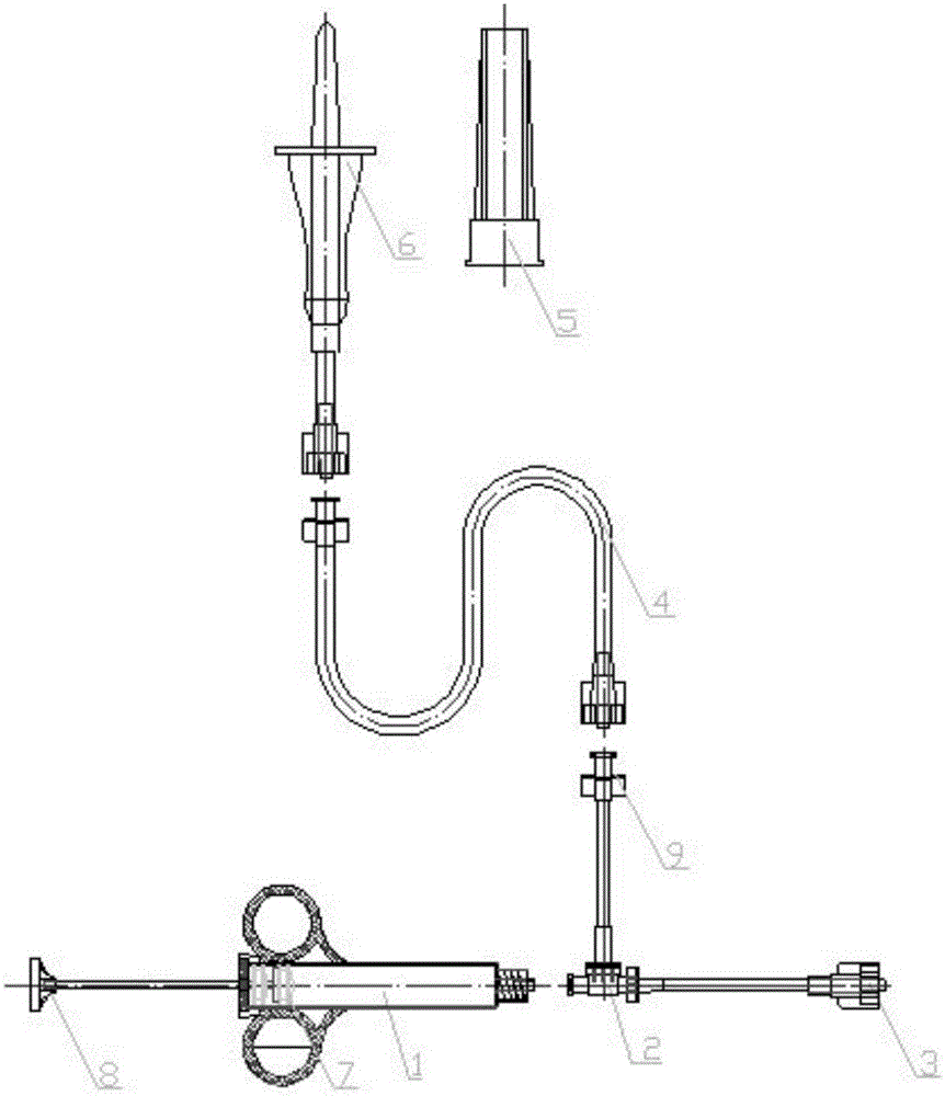
[0038] A vacuum injector 1 is connected to one end of the two-way check valve 2. The vacuum injector 1 includes an injection cavity and a push rod matching the injection cavity. The end of the push rod protruding into the injection cavity is provided with a double head Piston 7;
[0039] The liquid outlet 3 is an external conical Luer connector, and the external conical Luer connector is connected to one end of the two-way check valve 2;
[0040] One end of the two-way check valve 2 is connected to the endoscope through the outer conical Luer connector.
[0041] Wherein, the bottle insertion needle 6 is connected to the liquid inlet joint on the two-way check valve 2 through the liquid outlet joint; when sucking liq...
Embodiment 3
[0043] The liquid outlet unit includes,
[0044] The bypass line 4 is a hose connected to the outlet joint;
[0045] Two-way check valve 2, which is a three-way pipe structure, one end of the two-way check valve 2 is connected to the bypass pipeline 4 through a liquid inlet pipe, and the liquid inlet pipe port is provided with the liquid inlet joint, The liquid inlet connector is an inner conical Luer connector;
[0046] A vacuum injector 1 is connected to one end of the two-way check valve 2. The vacuum injector 1 includes an injection cavity and a push rod matching the injection cavity. The end of the push rod protruding into the injection cavity is provided with a double head Piston 7;
[0047] The liquid outlet 3 is an outer conical Luer connector, the outer conical Luer connector is connected to one end of the two-way check valve 2, and the outer conical Luer connector is used for connecting an endoscope;
[0048] One end of the two-way check valve 2 is connected to th...
PUM
 Abstract
Description
Claims
Application Information