Eureka AIR delivers breakthrough ideas for toughest innovation challenges, trusted by R&D personnel around the world.

Efficient desulphurization and dust removal device

A high-efficiency technology for desulfurization and dust removal, applied in the direction of combined devices, dispersed particle separation, chemical instruments and methods, etc., can solve the problems of low gas-liquid mass transfer efficiency between flue gas and slurry, difficulty in achieving high-efficiency desulfurization, and high investment cost. Avoiding gypsum rain, improving flue gas escape, low investment and operating costs

Inactive Publication Date: 2015-12-02
BEIJING CPCEP ENERGY CONSERVATION & ENVIRONMENTAL PROTECTION TECH CO LTD
View PDF6 Cites 5 Cited by
  • Summary
  • Abstract
  • Description
  • Claims
  • Application Information

AI Technical Summary

Problems solved by technology

[0002] In the existing desulfurization device, the flue gas entering the absorption tower is unevenly distributed on the cross-section of the tower, resulting in low gas-liquid mass transfer efficiency between the flue gas and the slurry, making it difficult to achieve efficient desulfurization
[0003] In order to improve the desulfurization efficiency, some researchers have adopted methods such as increasing the spray area and installing gas collecting rings or tower internal components near the tower wall to achieve efficient desulfurization. However, some of the above solutions have high energy consumption or high cost, and some are reliable. lower sex
[0004] At the same time, due to the small particle size of the dust in the flue gas entering the tower, there are still a large number of gypsum particles in the gypsum slurry, which leads to the formation of gypsum rain at the chimney outlet. Currently, three-layer ridge type demisters or two-layer The combination of ridge type + one-layer pipe type has higher investment cost

Method used


Image

  • Efficient desulphurization and dust removal device
  • Efficient desulphurization and dust removal device
  • Efficient desulphurization and dust removal device

Examples


Embodiment example

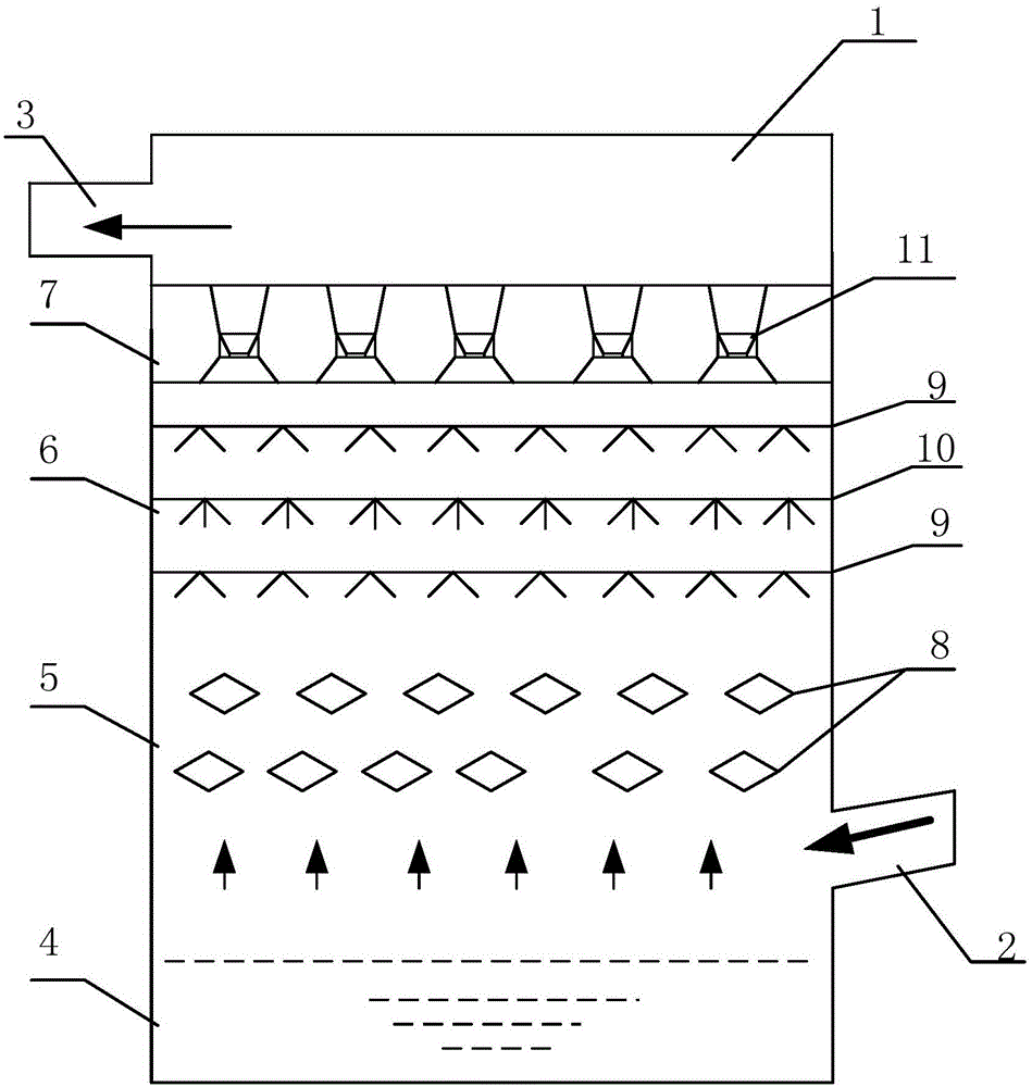
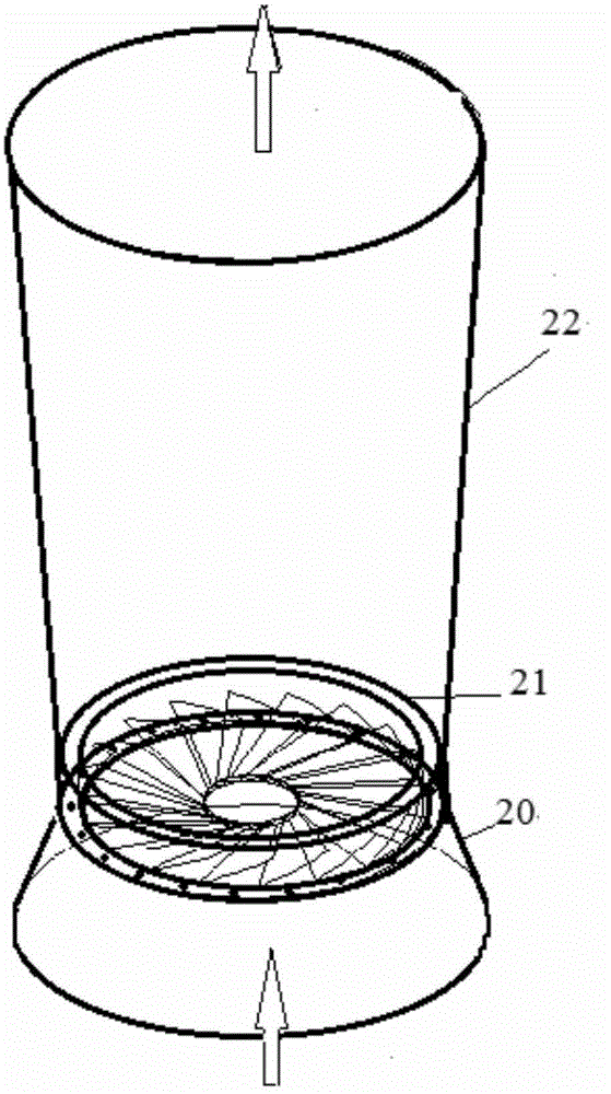
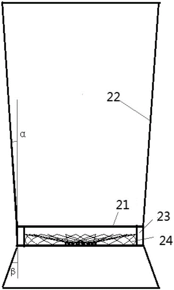
[0035] The inlet tapered section is a frustum-shaped structure with a vertex angle range of 15-25°. The diameter of the inlet when the flue gas flows through this section is larger than the exit diameter of the flue gas flow through this section; the throat swirl section is a cylindrical structure, and the flue gas The diameter of the inlet when the gas flows through this section is equal to the outlet diameter when the smoke flows through this section. The central plate in the swirl element is a solid plate, and the ratio of the diameter of the swirl element to the swirl element is 0.2 to 0.4. The number of swirl blades There are 18 pieces, and the radial angle is -10~-20°, and the elevation angle is 20~30°; the gradual expansion section of the outlet is a rounded frustum-shaped structure, and the apex angle ranges from 2 to 8°. When the flue gas flows through this section The inlet diameter is smaller than the outlet diameter for flue gas flow through the section. In additio...


PUM


Abstract

The invention discloses an efficient desulphurization and dust removal device which comprises an absorption tower shell (1). The lower portion of the side wall of the absorption tower shell (1) is connected with an inlet flue (2), and the upper portion of the side wall of the absorption tower shell (1) is connected with an outlet flue (3). A slurry pool area (4), a rhombus grid flow equalizing area (5), a spraying area (6) and a demisting area (7) are sequentially arranged inside the absorption tower shell (1) from bottom to top. The slurry pool area (4) is located below the inlet flue (2). The rhombus grid flow equalizing area (5), the spraying area (6) and the demisting area (7) are located between the inlet flue (2) and the outlet flue (3). The rhombus grid flow equalizing area (5) can adjust distribution of flue gas entering the absorption tower shell (1) from the inlet flue (2). The efficient desulphurization and dust removal device achieves efficient desulphurization in a tower and achieves the dust removal effect as well, and reduces system investment and manufacturing cost.

Description

technical field [0001] The invention relates to the technical field of flue gas desulfurization technology and equipment in the field of environmental protection, in particular to an absorption tower capable of realizing high-efficiency desulfurization and dust removal, which can be used in industries such as electric power, cement, metallurgy, and chemical industry. Background technique [0002] In the existing desulfurization device, the flue gas entering the absorption tower is unevenly distributed on the cross-section of the tower, resulting in low gas-liquid mass transfer efficiency between flue gas and slurry, making it difficult to achieve efficient desulfurization. [0003] In order to improve the desulfurization efficiency, some researchers have adopted methods such as increasing the spray area and installing gas collecting rings or tower internal components near the tower wall to achieve efficient desulfurization. However, some of the above solutions have high energ...

Claims


Application Information

Patent Timeline
IPC IPC(8): B01D50/00
Inventor 马志刚韩玉维江浩单选户白云峰初炜纳宏波黄晓芳王德俊陈雪刘亚郭少鹏刘洋
Owner BEIJING CPCEP ENERGY CONSERVATION & ENVIRONMENTAL PROTECTION TECH CO LTD
Why Eureka
Eureka Blog
Learn More