
A Method for Machining Curved Surface Shafts on a Profile Lathe with a Cutting Compensation Mechanism

A compensation mechanism and a technology for profiling lathes, applied in the field of profiling lathes, can solve the problems of low machining accuracy and short service life, and achieve the effects of reasonable structural design, high degree of automation, and easy realization.

Active Publication Date: 2017-07-07
马鞍山市恒泰重工机械有限公司
View PDF2 Cites 0 Cited by
  • Summary
  • Abstract
  • Description
  • Claims
  • Application Information

AI Technical Summary

Problems solved by technology

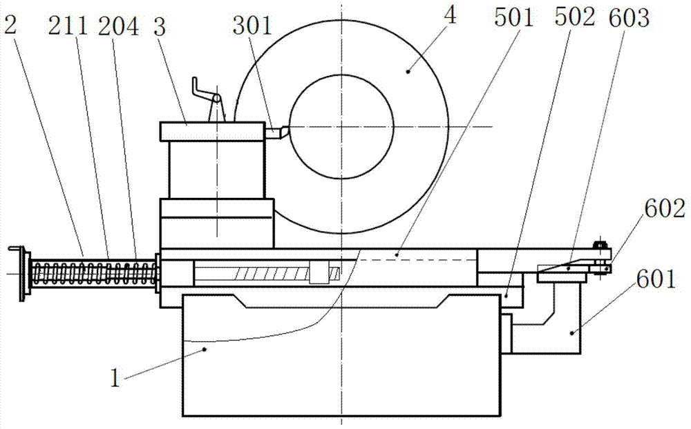
[0006] The purpose of the present invention is to overcome the disadvantages of low processing precision and short life of profiling lathes in the prior art, and provide a method for processing curved surface shafts on a profiling lathe with a cutting compensation mechanism. The technical solution of the present invention, through cutting compensation The mechanism compensates the cutting force during processing, which ensures sufficient cutting force, reduces the wear on the profiling mechanism, improves the processing accuracy and service life, and is easy to transform and realize, reducing production costs

Method used


Image

  • A Method for Machining Curved Surface Shafts on a Profile Lathe with a Cutting Compensation Mechanism
  • A Method for Machining Curved Surface Shafts on a Profile Lathe with a Cutting Compensation Mechanism
  • A Method for Machining Curved Surface Shafts on a Profile Lathe with a Cutting Compensation Mechanism

Examples


Embodiment 1

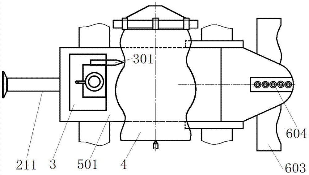
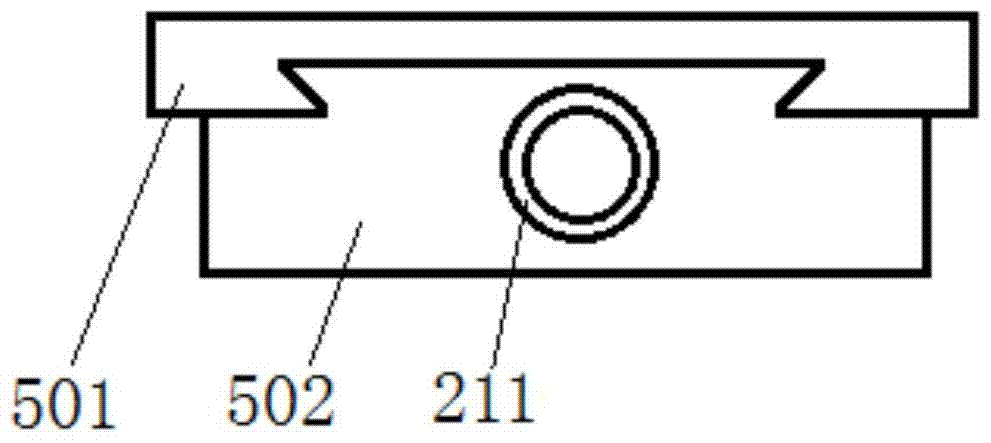
[0043] combine figure 1 and figure 2 , a method for processing a curved surface shaft on a profiling lathe with a cutting compensation mechanism in this embodiment, the profiling lathe used is mainly composed of a lathe body 1, a pull plate 501, a supporting plate 502, a tool holder 3, and a cutting compensation mechanism 2 And profiling mechanism etc. composition. Wherein, the supporting plate 502 and the lathe body 1 are driven by a screw, so that the supporting plate 502 slides longitudinally along the lathe body 1 , that is, moves along the axial direction of the workpiece 4 to be processed. Such as image 3 As shown, a tenon is provided on the supporting plate 502, and the lower part of the pulling plate 501 is a tenon-groove structure. The pulling plate 501 and the supporting plate 502 are slidably connected through the cooperation between the tenon and the tenon, and the pulling plate 501 can slide laterally along the supporting plate 502. . Fixing the knife seat 3...

Embodiment 2

[0054] A method for machining a curved surface shaft with a profiling lathe with a cutting compensation mechanism in this embodiment has the same basic structure as that of Embodiment 1, the difference being that in the outer sleeve groove 205 and the inner sleeve groove 207, the limit The width of the position bar 206 protruding to the linear sliding section is 0.25 times of the diameter of the stop bar 206, the outer groove inclined section 2051 and the inner groove inclined section 2071 are composed of a first inclined section and a second inclined section, the first inclined section and the second inclined section The straight-line sliding section is connected, and the included angle between the first inclined section and the direction of the straight-line sliding section is smaller than the included angle between the second inclined section and the direction of the straight-line sliding section. The purpose of switching the limit rod 206 can also be achieved through the tw...

Embodiment 3

[0056] A method for processing a curved shaft on a profiling lathe with a cutting compensation mechanism in this embodiment has the same basic structure as that of Embodiment 1, except that a dust cover 211 is placed on the outer circumference of the external compression spring 204 to prevent Dust enters between the outer sleeve 203 and the inner sleeve 208 to affect its slidability. A sliding sleeve 210 is arranged on the supporting plate 502, and the sliding sleeve 210 can prevent wear on the shaft rod 202 and ensure its slidability. Since the movement deformation of the external compression spring 204 exceeds 2D / 3, it will be difficult to provide the force required for the concave arc of the profiling surface, so the distance between the engaging section in the outer sleeve groove 205 and the engaging section in the inner sleeve groove 207 It can be set to 2D / 3, and the resistance compensated by the internal compression spring 209 does not exceed the maximum resistance exer...


PUM


Abstract

The invention discloses a method for machining a curved surface shaft through a copying lathe provided with a cutting compensation mechanism and belongs to the field of copying lathes. The copying lathe comprises a lathe body, a pull plate, a supporting plate and a tool apron. The supporting plate slides along the lathe body in the longitudinal direction, the pull plate is connected with the supporting plate in a sliding mode, the pull plate is made to slide along the supporting plate in the transverse direction, and the tool apron is fixed to the pull plate. The lathe further comprises the cutting compensation mechanism and a profiling mechanism. The profiling mechanism comprises a profiling depended wheel and a curved surface template. The profiling depended wheel is arranged in adjusting holes in the pull plate through a connection rod, and the cutting compensation mechanism controls the profiling depended wheel to be matched with the profiling face of the curved surface template through the pull plate. According to the copying lathe, the cutting compensation mechanism compensates the cutting force generated in the machining process, sufficient cutting force is guaranteed, abrasion to the profiling mechanism is alleviated, machining accuracy is improved, the service life is prolonged, reformation is achieved easily, and the production cost is lowered.

Description

technical field [0001] The invention relates to the technical field of profiling lathes, and more specifically relates to a method for machining curved surface shafts on a profiling lathe with a cutting compensation mechanism. Background technique [0002] The cylindrical surface can be easily processed on the workpiece with ordinary lathes and grinders, and the normal of the cylindrical surface is a straight line. However, it is difficult to process curved surfaces on workpieces with ordinary lathes and grinders. Therefore, for workpieces that require curved surface processing, CNC lathes are used to complete curved surface processing. For small and medium-sized enterprises, the price of CNC lathes is high, especially for large-scale shaft parts, it is necessary to purchase large-scale CNC lathes, which is difficult to bear due to the economic strength of small and medium-sized enterprises, resulting in the processing of curved surface shaft parts. [0003] After continuou...

Claims


Application Information

Patent Timeline
Patent Type & Authority Patents(China)
IPC IPC(8): B23B5/36
CPCB23B5/36
Inventor 周骏立陈道龙张彩红诸天江张万明
Owner 马鞍山市恒泰重工机械有限公司
Learn More