Thin-wall piece mechanical fixed force clamping self-locking device and method

A self-locking device, mechanical technology, applied in the direction of clamping device, positioning device, metal processing machinery parts, etc., can solve the problems of shrinkage cavity, easy deformation of aperture, easy vibration of knife, etc., to reduce difficulty and cost, prevent direct Contact, enhance the effect of adjustment range

Active Publication Date: 2015-12-02
菲斯达精密工业部件(苏州)有限公司
View PDF9 Cites 2 Cited by
  • Summary
  • Abstract
  • Description
  • Claims
  • Application Information

AI Technical Summary

Problems solved by technology

[0002] In the existing machining process of thin-walled parts, the diameter, roundness and cylindricity of the machined holes are not easy to guarantee, and at the same time, the clamping force of the clamping device of the existing machining thin-walled parts machinery is not easy to control , If the force is too large, it is easy to cause deformation of the aperture and poor shrinkage. If the force is too small, it is easy to vibrate the tool during processing, resulting in poor hole diameter and roughness. At the same time, the existing fixture design space is small, which is not conducive to the installation of hydraulic floating support cylinders. In addition, there is little room for adjusting the clamping force of the existing support cylinder, and the price is relatively expensive.

Method used


Image

  • Thin-wall piece mechanical fixed force clamping self-locking device and method
  • Thin-wall piece mechanical fixed force clamping self-locking device and method

Examples


Embodiment Construction

[0020] The following will clearly and completely describe the technical solutions in the embodiments of the present invention with reference to the accompanying drawings in the embodiments of the present invention. Obviously, the described embodiments are only some, not all, embodiments of the present invention. Based on the embodiments of the present invention, all other embodiments obtained by persons of ordinary skill in the art without making creative efforts belong to the protection scope of the present invention.

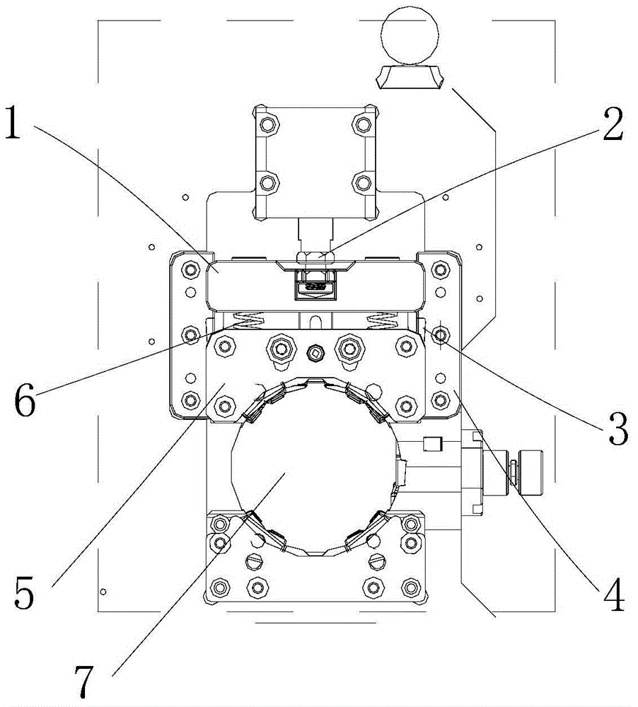
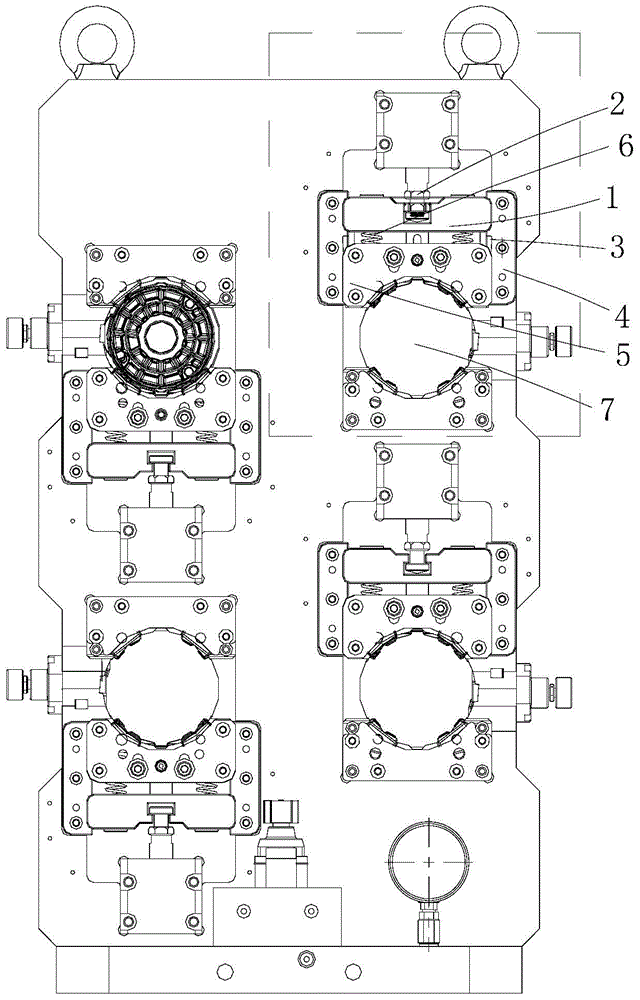
[0021] see Figure 1-2 , the present invention provides a technical solution: a mechanical clamping and self-locking device for thin-walled parts, including an oil cylinder push rod 1, an adjusting bolt 2, a wedge block 3, a guide block 4, a pressing block 5, and a spring 6 and the clamping ring 7; the top cavity of the cylinder push rod 1 is equipped with an adjusting bolt 2, the bottom left and right sides of the cylinder push rod 1 are equipped with springs...


PUM


Abstract

The invention discloses a thin-wall piece mechanical fixed force clamping self-locking device and a method. The device comprises an oil cylinder push rod, an adjusting bolt, an inclined wedge, guide blocks, a pressing block, a spring and a clamping ring, wherein the adjusting bolt is mounted in an inner cavity at the top of the oil cylinder push rod; the pressing block is mounted at the bottom of the spring; the guide blocks are mounted at the left and right sides of the back surface of the pressing block; and the clamping ring is mounted at the bottom of the pressing block. The adjusting bolt, the inclined wedge and the spring mounted on the thin-wall piece mechanical fixed force clamping self-locking device effectively enhance the adjusting amplitude of tool clamping force of the clamping self-locking device; meanwhile, the thin-wall piece mechanical fixed force clamping self-locking device adopts a mechanical fixed force clamping self-locking device, so that the tool design difficulty and cost are reduced, and the capacity in the product size machining process is improved; and the clamping self-locking device is simple in operation, and greatly reduces the ability requirements of operators.

Description

technical field [0001] The invention relates to the technical field of machining fixtures, in particular to a mechanical fixing force clamping self-locking device and method for thin-walled parts. Background technique [0002] In the existing machining process of thin-walled parts, the diameter, roundness and cylindricity of the machined holes are not easy to guarantee, and at the same time, the clamping force of the clamping device of the existing machining thin-walled parts machinery is not easy to control , If the force is too large, it is easy to cause deformation of the aperture and poor shrinkage. If the force is too small, it is easy to vibrate the tool during processing, resulting in poor hole diameter and roughness. At the same time, the existing fixture design space is small, which is not conducive to the installation of hydraulic floating support cylinders. In addition, there is little room for adjusting the clamping force of the existing support cylinder, and the...

Claims


Application Information

Patent Timeline
Patent Type & Authority Applications(China)
IPC IPC(8): B23Q3/00
CPCB23Q3/00B23Q2703/04B23Q2703/10
Inventor 何玉宏
Owner 菲斯达精密工业部件(苏州)有限公司
Why Eureka
Try Eureka