
Multi-stage coaxial staggered extrusion device

A staggered, coaxial technology, applied in the field of crushing, material grinding, mixing and extrusion molding equipment, can solve the extrusion, crushing and grinding force is limited, not suitable for strong crushing and grinding, manufacturing and use costs Advanced problems, to achieve the effect of improving efficiency and grinding quality, compact structure, and simplified machine structure

Active Publication Date: 2017-09-26
盐城智能终端产业园区开发运营有限公司
View PDF8 Cites 0 Cited by
  • Summary
  • Abstract
  • Description
  • Claims
  • Application Information

AI Technical Summary

Problems solved by technology

However, because it does not have the function of grinding and crushing on the end surface, its extrusion, crushing and grinding force is limited, so it is not suitable for strong crushing and grinding; and its scope of application is limited, it can only be used for crushing and grinding of ultra-fine materials. Materials with granularity and coarser particles cannot be processed
[0009] Chinese patent CN 101890799 B "combined impeller disc type extrusion plasticization method and device" adopts a structure in which a plurality of fixed impeller discs and rotating impeller discs are stacked together, so that the material passes through the multiple staggered disc gaps and When the blade passes through the material channel, it is mixed, crushed, ground and softened step by step, which improves the quality of plasticization, but this structure is too complicated, the cost of manufacturing and use is too high, and the axial dimension is still large

Method used


Image

  • Multi-stage coaxial staggered extrusion device
  • Multi-stage coaxial staggered extrusion device
  • Multi-stage coaxial staggered extrusion device

Examples


Embodiment Construction

[0031] The specific embodiments of the present invention will be further described below in conjunction with the accompanying drawings. It should be noted here that the descriptions of these embodiments are used to help understand the present invention, but are not intended to limit the present invention. In addition, the technical features involved in the various embodiments of the present invention described below may be combined with each other as long as they do not constitute a conflict with each other.

[0032] In the description of the present invention, the orientations or positional relationships indicated by the terms "left", "right", etc. are based on the orientations or positional relationships shown in the drawings. construction and operation, therefore, should not be construed as limiting the invention.

[0033] In the description of the present invention, the terms "first" and "second" are used for descriptive purposes only, and should not be understood as indi...


PUM


Abstract

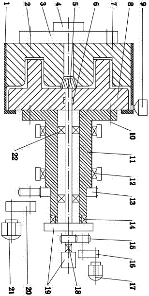
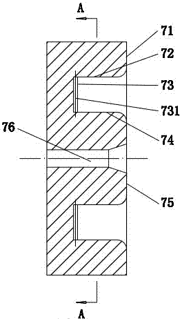
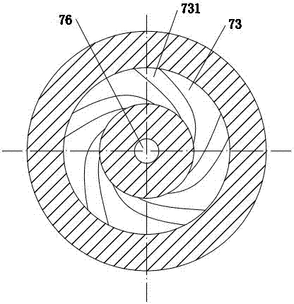
The invention relates to a multistage coaxial alternating type extrusion device. The multistage coaxial alternating type extrusion device comprises a machine cylinder, a flange plate, an extrusion head, a taper blade shaft, a fixed wheel, a rotary wheel, a hopper, a rotary wheel transmission shaft, a first radial bearing, a second radial bearing, a first thrust bearing, a second thrust bearing, a first gear, a second gear, a first transmission mechanism, a second transmission mechanism, a first motor, a second motor and a base. The multistage coaxial alternating type extrusion device is characterized in that the right side of the fixed wheel and the left side of the rotary wheel are matched in a staggered mode; multiple stages of circumference screw groove sets and multiple stages of end surface screw groove sets are sequentially formed in the matching part from the outer circle to the center, so that multiple stages of circumference extrusion areas and multiple stages of end surface extrusion areas are formed; the multiple stages of circumference screw groove sets and the multiple stages of end surface screw groove sets alternate in sequence to form a material smashing, grinding, extruding, shearing, mixing and conveying channel; the discharge port of the hopper is communicated with the first stage of circumference screw groove set in the outer cylinder of the rotary wheel. The multistage coaxial alternating type extrusion device has the advantages that the material plasticizing quality and capacity can be improved, the problems of a screw cantilever of a screw extruder are solved, the machine structure is simplified, the length is reduced, and the cost of manufacture, use and maintenance is low.

Description

technical field [0001] The invention relates to equipment for grinding, crushing, mixing and extruding various inorganic materials and polymer materials, in particular to a multi-stage coaxial staggered extrusion device, which belongs to the equipment for grinding, crushing and mixing of materials. Refining and extrusion molding equipment technical field. Background technique [0002] In rubber, plastic and other industrial fields, grinding, mixing and extrusion molding machines are important equipment. Ordinary single-screw extruders have limited functions for crushing, shearing and grinding materials, and the structure of screw extruders is a cantilever beam structure, which is often easily affected by its own gravity, axial and radial thrust of materials. The reason is the friction and wear with the machine barrel, especially when the material is subjected to strong grinding, this shortcoming is even more prominent. [0003] In order to overcome the deficiencies of the ...

Claims


Application Information

Patent Timeline
Patent Type & Authority Patents(China)
IPC IPC(8): B29C47/36B29C47/58B29C48/50
CPCB29C48/375B29C48/50
Inventor 陈学锋凃明霞徐言生胡建国柯美元曾宪荣
Owner 盐城智能终端产业园区开发运营有限公司
Learn More